参数资料
| 型号: | ISL6617IRZ |
| 厂商: | Intersil |
| 文件页数: | 11/15页 |
| 文件大小: | 0K |
| 描述: | IC PWM DOUBLER MONITOR 10DFN |
| 标准包装: | 100 |
| 应用: | PWM Doubler |
| 电流 - 电源: | 6mA |
| 电源电压: | 4.5 V ~ 5.5 V |
| 工作温度: | -40°C ~ 85°C |
| 安装类型: | * |
| 封装/外壳: | * |
| 供应商设备封装: | * |
| 包装: | * |
�� �
�
�ISL6617�
�I� (� s� )�
�When� the� doubler� operates� in� interleaving� mode,� the�
�PWM� controller� frequency� should� be� set� at� two� times� the�
�desired� phase� frequency� (F� SW� ).� Since� the� input� PWM�
�pulse� is� divided� into� half� to� feed� into� each� phase� of� the�
�doubler,� the� operational� duty� cycle� of� each� phase� should�
�be� less� than� 50%.� In� synchronous� mode,� the� PWM�
�controller� should� be� operated� at� the� same� frequency� as�
�the� desired� phase� frequency.� In� this� mode,� the� allowable�
�duty� cycle� is� up� to� 100%.� For� cascaded� interleaving,� the�
�controller� switching� frequency� needs� to� be� set� at� four�
�times� the� phase� frequency.� During� cascaded� operation,�
�the� maximum� allowable� duty� cycle� will� be� less� than� 25%.�
�All� of� the� maximum� allowable� duty� cycle� numbers�
�referenced� assume� that� the� PWM� controller� can� send� out�
�a� 100%� duty� cycle� pulse.� In� many� cases,� this� is� not�
�achievable� because� the� controller� needs� time� to� reset� it's�
�The� internal� circuitry,� shown� in� Figures� 10� and� 11,�
�represents� one� channel.� This� circuitry� is� repeated� for�
�each� channel� in� the� doubler.� The� input� bias� current� of� the�
�current� sensing� amplifier� is� typically� 60nA;� less� than� 5k� Ω�
�input� impedance� is� preferred� to� minimize� the� offset� error.�
�In� addition,� the� common� mode� input� voltage� to� the�
�amplifier� should� be� less� than� VCC-3V.�
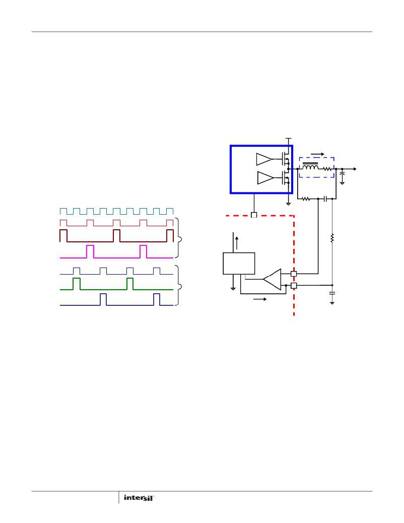
�A.� INDUCTOR� DCR� SENSING�
�An� inductor’s� winding� is� characteristic� of� a� distributed�
�resistance,� as� measured� by� the� DCR� (Direct� Current�
�Resistance)� parameter.� Consider� the� inductor� DCR� as� a�
�separate� lumped� quantity,� as� shown� in� Figure� 10.�
�V� IN�
�L�
�DCR�
�internal� sawtooth� ramp� or� internal� max� duty� limit.�
�However,� the� fixed� 120ns� extension� of� interleaving� mode�
�2� helps� recover� the� typical� 1%� duty� cycle� loss� associated�
�with� the� ramp� reset� time.� In� addition,� Intersil� has�
�developed� a� dedicated� controller,� the� ISL6336G� with�
�90%� duty� cycle,� to� work� with� the� ISL6617� for� high-phase�
�POWER�
�STAGE�
�L�
�INDUCTOR�
�V� L�
�V� C� (s)�
�V� OUT�
�C� OUT�
�count� and� overclocking� applications.�
�PWM1�
�PWMA�
�PWM1A�
�PWMA/B�
�ISL6617�
�I� A/B�
�R�
�C�
�R� ISEN(A/B)�
�PWM1B�
�CURRENT�
�SENSE�
�PWMB�
�+�
�ISEN-(A/B)�
�PWM1C�
�-�
�ISEN+(A/B)�
�C� T�
�I� SEN� =� I� ------------------�
�L� R�
�V� RAMP�
�V� RAMP_EFFECTIVE� =� --------------------�
�D� MAX�
�V� L� (� s� )� =� I� L� ?� (� s� ?� L� +� DCR� )�
�?� s� ?� -------------� +� 1� ?� ?� (� DCR� ?� I� )�
�V� C� (� s� )� =� ---------------------------------------------------------------------�
�PWM1D�
�FIGURE� 9.� CASCADED� DOUBLER� OPERATIONAL�
�WAVEFORMS�
�To� properly� compensate� the� system� that� uses� phase�
�doublers,� the� effective� system� sawtooth� to� calculate� the�
�modulator� gain� should� factor� in� the� duty� cycle� limitation�
�(D� MAX� )� as� Equation� 1.� For� instance,� when� using�
�ISL6336G� and� ISL6617s� in� cascaded� interleaving� mode,�
�the� effective� sawtooth� amplitude� should� be� scaled� as�
�3V/22.5%� =� 13.33V.�
�(EQ.� 1)�
�Current� Sensing�
�The� ISL6617� senses� current� continuously� for� fast�
�response.� The� ISL6617� supports� inductor� DCR� sensing,�
�or� resistive� sensing� techniques.� The� associated� channel�
�current� sense� amplifier� uses� the� ISEN� inputs� to�
�reproduce� a� signal� proportional� to� the� inductor� current,�
�I� L� .� The� sensed� current,� I� SEN� ,� is� proportional� to� the�
�inductor� current.� The� sensed� current� is� used� for� current�
�balance� and� load-line� regulation.�
�11�
�DCR�
�ISEN�
�FIGURE� 10.� DCR� SENSING� CONFIGURATION�
�The� channel� current� I� L� ,� flowing� through� the� inductor,� will�
�also� pass� through� the� DCR.� Equation� 2� shows� the� s-�
�domain� equivalent� voltage� across� the� inductor� V� L� .�
�(EQ.� 2)�
�A� simple� R-C� network� across� the� inductor� extracts� the�
�DCR� voltage,� as� shown� in� Figure� 10.�
�The� voltage� on� the� capacitor� V� C� ,� can� be� shown� to� be�
�proportional� to� the� channel� current� I� L� .� See� Equation� 3.�
�L�
�?� DCR� ?� L� (EQ.� 3)�
�(� s� ?� RC� +� 1� )�
�If� the� R-C� network� components� are� selected� such� that�
�the� RC� time� constant� matches� the� inductor� time� constant�
�(RC� =� L/DCR),� the� voltage� across� the� capacitor� V� C� is�
�equal� to� the� voltage� drop� across� the� DCR,� i.e.,�
�proportional� to� the� channel� current.�
�With� the� internal� low-offset� current� amplifier,� the�
�capacitor� voltage� V� C� is� replicated� across� the� sense�
�FN7564.0�
�February� 4,� 2010�
�相关PDF资料 |
PDF描述 |
|---|---|
| ISL6627IRZ-T | IC CONTROLLER VR11.1 VR12 10DFN |
| ISL6719ARZ-T | IC REG LDO ADJ .1A 9-DFN |
| ISL6720AARZ | IC REG LDO 5V/ADJ 11-DFN |
| ISL6721AAVZ | IC REG CTRLR PWM CM 16-TSSOP |
| ISL6721AV | IC REG CTRLR PWM CM 16-TSSOP |
相关代理商/技术参数 |
参数描述 |
|---|---|
| ISL6617IRZ-T | 功能描述:功率驱动器IC PHS SPLITTER INDUSTRIAL 10LD 3X3 RoHS:否 制造商:Micrel 产品:MOSFET Gate Drivers 类型:Low Cost High or Low Side MOSFET Driver 上升时间: 下降时间: 电源电压-最大:30 V 电源电压-最小:2.75 V 电源电流: 最大功率耗散: 最大工作温度:+ 85 C 安装风格:SMD/SMT 封装 / 箱体:SOIC-8 封装:Tube |
| ISL6620ACBZ | 功能描述:IC SYNC RECT MOSFET DRVR 8-SOIC RoHS:是 类别:集成电路 (IC) >> PMIC - MOSFET,电桥驱动器 - 外部开关 系列:- 标准包装:95 系列:- 配置:半桥 输入类型:PWM 延迟时间:25ns 电流 - 峰:1.6A 配置数:1 输出数:2 高端电压 - 最大(自引导启动):118V 电源电压:9 V ~ 14 V 工作温度:-40°C ~ 125°C 安装类型:表面贴装 封装/外壳:8-SOIC(0.154",3.90mm 宽) 供应商设备封装:8-SOIC 包装:管件 产品目录页面:1282 (CN2011-ZH PDF) 其它名称:*LM5104M*LM5104M/NOPBLM5104M |
| ISL6620ACBZ-T | 功能描述:IC MOSFET DVR SYNC BUCK 8-SOIC RoHS:是 类别:集成电路 (IC) >> PMIC - MOSFET,电桥驱动器 - 外部开关 系列:- 标准包装:6,000 系列:* |
| ISL6620ACRZ | 功能描述:IC SYNC RECT MOSFET DRVR 10-DFN RoHS:是 类别:集成电路 (IC) >> PMIC - MOSFET,电桥驱动器 - 外部开关 系列:- 标准包装:95 系列:- 配置:半桥 输入类型:PWM 延迟时间:25ns 电流 - 峰:1.6A 配置数:1 输出数:2 高端电压 - 最大(自引导启动):118V 电源电压:9 V ~ 14 V 工作温度:-40°C ~ 125°C 安装类型:表面贴装 封装/外壳:8-SOIC(0.154",3.90mm 宽) 供应商设备封装:8-SOIC 包装:管件 产品目录页面:1282 (CN2011-ZH PDF) 其它名称:*LM5104M*LM5104M/NOPBLM5104M |
| ISL6620ACRZ-T | 功能描述:IC MOSFET DVR SYNC BUCK 10-DFN RoHS:是 类别:集成电路 (IC) >> PMIC - MOSFET,电桥驱动器 - 外部开关 系列:- 标准包装:6,000 系列:* |
发布紧急采购,3分钟左右您将得到回复。