- 您现在的位置:买卖IC网 > PDF目录17644 > ISL9443IRZ-T (Intersil)IC REG CTRLR BUCK PWM CM 32-QFN PDF资料下载
参数资料
| 型号: | ISL9443IRZ-T |
| 厂商: | Intersil |
| 文件页数: | 20/23页 |
| 文件大小: | 0K |
| 描述: | IC REG CTRLR BUCK PWM CM 32-QFN |
| 标准包装: | 6,000 |
| PWM 型: | 电流模式 |
| 输出数: | 3 |
| 频率 - 最大: | 1.32MHz |
| 电源电压: | 4.5 V ~ 26 V |
| 降压: | 是 |
| 升压: | 无 |
| 回扫: | 无 |
| 反相: | 无 |
| 倍增器: | 无 |
| 除法器: | 无 |
| Cuk: | 无 |
| 隔离: | 无 |
| 工作温度: | -40°C ~ 85°C |
| 封装/外壳: | * |
| 包装: | * |
�� �
�
�ISL9443�
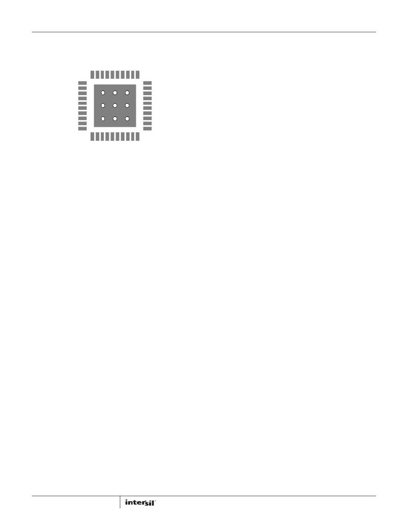
�General� PowerPAD� Design� Considerations�
�The� following� is� an� example� of� how� to� use� vias� to� remove� heat�
�form� the� IC.�
�Output� Inductor� Selection�
�The� PWM� converters� require� output� inductors.� The� output�
�inductor� is� selected� to� meet� the� output� voltage� ripple�
�requirements.� The� inductor� value� determines� the� converter’s�
�ripple� current� and� the� ripple� voltage� is� a� function� of� the� ripple�
�current� and� the� output� capacitor(s)� ESR.� The� ripple� voltage�
�expression� is� given� in� the� capacitor� selection� section� and� the�
�ripple� current� is� approximated� by� Equation� 14:�
�(� V� IN� –� V� OUT� )� (� V� OUT� )�
�Δ� I� L� =� ---------------------------------------------------�
�(� f� S� )� (� L� )� (� V� IN� )�
�(EQ.� 14)�
�Output� Capacitor� Selection�
�The� output� capacitors� for� each� output� have� unique� requirements.�
�(� L� O� )� (� I� TRAN� )�
�2� (� V� IN� –� V� O� )� (� DV� OUT� )�
�(� I� O� )� (� r� DS� (� ON� )� )� (� V� OUT� )�
�(� I� O� )� (� V� IN� )� (� t� SW� )� (� F� SW� )�
�V� IN�
�(� I� O� )� (� r� DS� (� ON� )� )� (� V� IN� –� V� OUT� )�
�P� LOWER� =� ------------------------------------------------------------------------�
�V� IN�
�V� RIPPLE� =� Δ� I� L� (� ESR� )�
�FIGURE� 23.� PCB� VIA� PATTERN�
�It� is� recommended� to� fill� the� thermal� pad� area� with� vias.� A� typical�
�via� array� fills� the� thermal� pad� foot� print� such� that� their� centers�
�are� 3x� the� radius� apart� from� each� other.� Keep� the� vias� small� but�
�not� so� small� that� their� inside� diameter� prevents� solder� wicking�
�through� during� reflow.�
�Connect� all� vias� to� the� ground� plane.� It� is� important� the� vias� have�
�a� low� thermal� resistance� for� efficient� heat� transfer.� It� is�
�important� to� have� a� complete� connection� of� the� plated-through�
�hole� to� each� plane.�
�Component� Selection� Guideline�
�MOSFET� Considerations�
�The� logic� level� MOSFETs� are� chosen� for� optimum� efficiency� given�
�the� potentially� wide� input� voltage� range� and� output� power�
�requirements.� Two� N-Channel� MOSFETs� are� used� in� each� of� the�
�synchronous-rectified� buck� converters� for� the� 3� PWM� outputs.�
�These� MOSFETs� should� be� selected� based� upon� r� DS(ON)� ,� gate�
�supply� requirements,� and� thermal� management� considerations.�
�The� power� dissipation� includes� two� loss� components;� conduction�
�loss� and� switching� loss.� These� losses� are� distributed� between� the�
�upper� and� lower� MOSFETs� according� to� duty� cycle� (see� the�
�following� equations).� The� conduction� losses� are� the� main�
�component� of� power� dissipation� for� the� lower� MOSFETs.� Only� the�
�upper� MOSFET� has� significant� switching� losses,� since� the� lower�
�device� turns� on� and� off� into� near� zero� voltage.� The� equations�
�assume� linear� voltage-current� transitions� and� do� not� model�
�power� loss� due� to� the� reverse-recovery� of� the� lower� MOSFET’s�
�body� diode.�
�2�
�2�
�P� UPPER� =� ----------------------------------------------------------� +� --------------------------------------------------------�
�(EQ.� 12)�
�2�
�(EQ.� 13)�
�A� large� gate-charge� increases� the� switching� time,� t� SW� ,� which�
�increases� the� upper� MOSFETs’� switching� losses.� Ensure� that� both�
�MOSFETs� are� within� their� maximum� junction� temperature� at� high�
�ambient� temperature� by� calculating� the� temperature� rise�
�according� to� package� thermal-resistance� specifications.�
�20�
�In� general,� the� output� capacitors� should� be� selected� to� meet� the�
�dynamic� regulation� requirements� including� ripple� voltage� and�
�load� transients.� Selection� of� output� capacitors� is� also� dependent�
�on� the� output� inductor,� so� some� inductor� analysis� is� required� to�
�select� the� output� capacitors.�
�One� of� the� parameters� limiting� the� converter’s� response� to� a� load�
�transient� is� the� time� required� for� the� inductor� current� to� slew� to�
�its� new� level.� The� ISL9443� will� provide� either� 0%� or� maximum�
�duty� cycle� in� response� to� a� load� transient.�
�The� response� time� is� the� time� interval� required� to� slew� the�
�inductor� current� from� an� initial� current� value� to� the� load� current�
�level.� During� this� interval� the� difference� between� the� inductor�
�current� and� the� transient� current� level� must� be� supplied� by� the�
�output� capacitor(s).� Minimizing� the� response� time� can� minimize�
�the� output� capacitance� required.� Also,� if� the� load� transient� rise�
�time� is� slower� than� the� inductor� response� time,� as� in� a� hard� drive�
�or� CD� drive,� it� reduces� the� requirement� on� the� output� capacitor.�
�The� maximum� capacitor� value� required� to� provide� the� full,� rising�
�step,� transient� load� current� during� the� response� time� of� the�
�inductor� is:�
�2�
�C� OUT� =� -----------------------------------------------------� (EQ.� 15)�
�Where� C� OUT� is� the� output� capacitor(s)� required,� L� O� is� the� output�
�inductor,� I� TRAN� is� the� transient� load� current� step,� V� IN� is� the� input�
�voltage,� V� O� is� output� voltage,� and� DV� OUT� is� the� drop� in� output�
�voltage� allowed� during� the� load� transient.�
�High� frequency� capacitors� initially� supply� the� transient� current�
�and� slow� the� load� rate-of-change� seen� by� the� bulk� capacitors.� The�
�bulk� filter� capacitor� values� are� generally� determined� by� the� ESR�
�(Equivalent� Series� Resistance)� and� voltage� rating� requirements�
�as� well� as� actual� capacitance� requirements.�
�The� output� voltage� ripple� is� due� to� the� inductor� ripple� current� and�
�the� ESR� of� the� output� capacitors� as� defined� by:�
�(EQ.� 16)�
���as� close� to� the� power� pins� of� the� load� as� physically� possible.� Be�
�careful� not� to� add� inductance� in� the� circuit� board� wiring� that�
�could� cancel� the� usefulness� of� these� low� inductance�
�components.� Consult� with� the� manufacturer� of� the� load� circuitry�
�for� specific� decoupling� requirements.�
�FN7663.1�
�February� 24,� 2012�
�相关PDF资料 |
PDF描述 |
|---|---|
| FOXSDLF/221-20 | CRYSTAL 22.1184 MHZ 20PF SMD |
| ZL2004ALNFT1 | IC REG CTRLR BUCK SYNC ADJ 32QFN |
| SBG3030CT-T | DIODE SCHOTTKY CC 30V 30A D2-PAK |
| FOXSDLF/115-20 | CRYSTAL 11.0592 MHZ 20PF SMD |
| ISL62392CIRTZ-T | IC PWR SUPPLY CTRLR 28TQFN |
相关代理商/技术参数 |
参数描述 |
|---|---|
| ISL9443IRZ-T7A | 功能描述:软开关 PWM 控制器 ISL9443 TRIPLE STEP CONTRLR IMVP-6. 32LD RoHS:否 制造商:Fairchild Semiconductor 输出端数量: 输出电流: 开关频率: 工作电源电压:30 V 电源电流: 最大工作温度:+ 105 C 最小工作温度:- 40 C 安装风格:SMD/SMT 封装 / 箱体:SOIC-8 封装:Reel |
| ISL9443IRZ-T7AS2750 | 制造商:Intersil Corporation 功能描述:ISL9443 TRIPLE, STEP- DOWN PWM CONTROLLER IMVP-6. 32 LD MLFP - Tape and Reel |
| ISL9443IRZ-TS2750 | 制造商:Intersil Corporation 功能描述:PB FREE. ISL9443 TRIPLE, STEP- DOWN PWM CONTROLLER IMVP-6. 3 - Tape and Reel |
| ISL9444CRZ | 制造商:Intersil Corporation 功能描述:PB FREE. ISL9444 TRIPLE, STEP- DOWN PWM CONTROLLER IMVP-6. 4 - Rail/Tube 制造商:Intersil Corporation 功能描述:IC REG CTRLR BUCK PWM CM 32-QFN 制造商:Intersil 功能描述:Pb Free. ISL9444 Tri ple, Step- Down PWM |
| ISL9444CRZ-T | 制造商:Intersil Corporation 功能描述:PB FREE. ISL9444 TRIPLE, STEP- DOWN PWM CONTROLLER IMVP-6. 4 - Tape and Reel 制造商:Intersil Corporation 功能描述:IC REG CTRLR BUCK PWM CM 32-QFN 制造商:Intersil 功能描述:Pb Free. ISL9444 Tri ple, Step- Down PWM |
发布紧急采购,3分钟左右您将得到回复。