参数资料
| 型号: | ISL9444IRZ |
| 厂商: | Intersil |
| 文件页数: | 18/24页 |
| 文件大小: | 0K |
| 描述: | IC REG CTRLR BUCK PWM CM 40-QFN |
| 标准包装: | 60 |
| PWM 型: | 电流模式 |
| 输出数: | 3 |
| 频率 - 最大: | 1.32MHz |
| 电源电压: | 4.5 V ~ 28 V |
| 降压: | 是 |
| 升压: | 无 |
| 回扫: | 无 |
| 反相: | 无 |
| 倍增器: | 无 |
| 除法器: | 无 |
| Cuk: | 无 |
| 隔离: | 无 |
| 工作温度: | -40°C ~ 85°C |
| 封装/外壳: | 40-VFQFN 裸露焊盘 |
| 包装: | 管件 |
�� �
�
�ISL9444�
�reduced� RMS� ripple� current� and� input� voltage� ripple.� This�
�reduces� the� required� input� capacitor� ripple� current� rating,�
�allowing� fewer� or� less� expensive� capacitors,� and� reducing� the�
�shielding� requirements� for� EMI.� The� typical� operating� curves� show�
�VCC_5V�
�OPTIONAL�
�EXTERNAL�
�SCHOTTKY�
�VIN�
�the� synchronized� 180°� out-of-phase� operation.�
�Power� Failure� Monitor�
�The� ISL9444� has� a� Power-Failure� Monitor� that� helps� to� monitor�
�an� additional� critical� voltage� on� the� Power-Fail� Input� (PFI)� pin.� For�
�example,� the� PFI� pin� could� be� used� to� provide� an� early� power-fail�
�warning,� detect� a� low-battery� condition,� or� simply� monitor� a�
�power� supply.� An� external� resistor� divider� network� is� needed� to�
�provide� monitoring� of� voltages� greater� than� 1.22V.� The� threshold�
�voltage� is� set� according� to� Equation� 6� (see� Typical� Application� on�
�page� 7).�
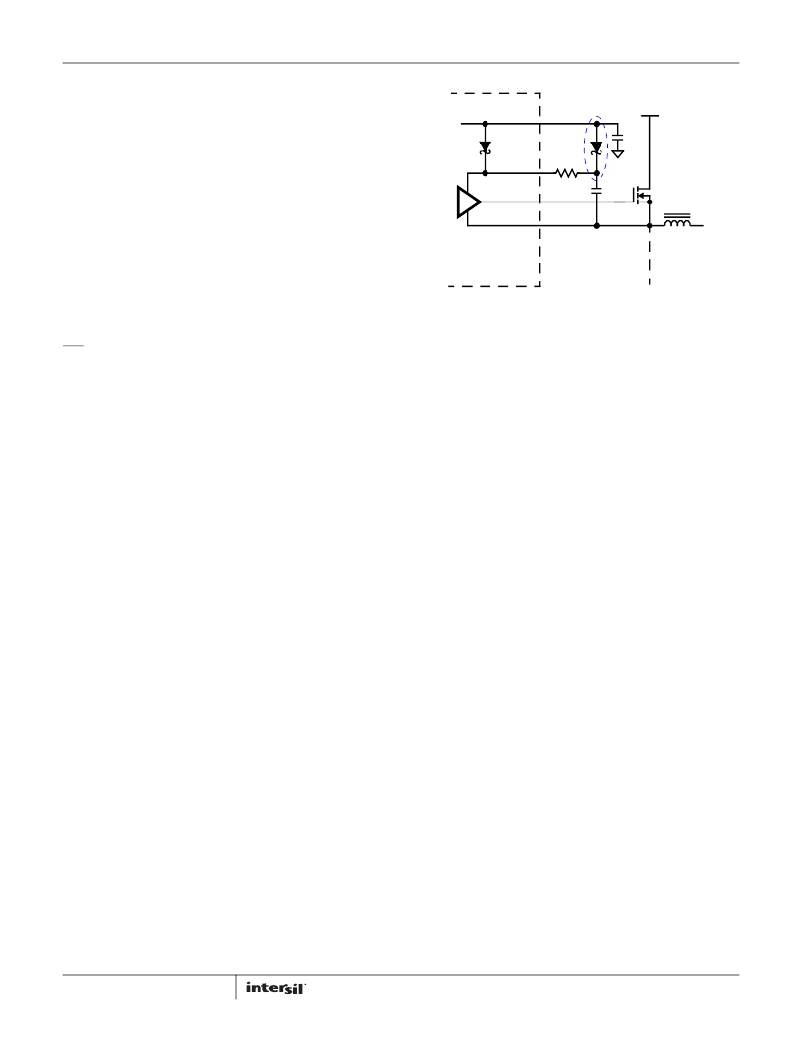
�BOOT�
�UGATE�
�PHASE�
�ISL9444�
�R� BOOT�
�C� B�
�VPFITH� =� 1.22V� � -----------------------------�
�(EQ.� 6)�
�Q� GATE�
�C� BOOT� ≥� ---------------------�
�R14� +� R15�
�R15�
�PFO� goes� low� whenever� the� PFI� pin� voltage� is� less� than� the� 1.22V�
�threshold� voltage.�
�Gate� Control� Logic�
�The� gate� control� logic� translates� generated� PWM� signals� into� gate�
�drive� signals� providing� amplification,� level� shifting� and�
�shoot-through� protection.� The� gate� drivers� have� circuitry� that� helps�
�optimize� the� IC� performance� over� a� wide� range� of� operational�
�conditions.� As� MOSFET� switching� times� can� vary� dramatically� from�
�type� to� type� and� with� input� voltage,� the� gate� control� logic� provides�
�adaptive� dead� time� by� monitoring� real� gate� waveforms� of� both� the�
�upper� and� the� lower� MOSFETs.� Shoot-through� control� logic� provides�
�a� 16ns� dead-time� to� ensure� that� both� the� upper� and� lower� MOSFETs�
�will� not� turn� on� simultaneously� causing� a� shoot-through� condition.�
�Gate� Drivers�
�The� low-side� gate� drivers� are� supplied� from� VCC_5V� and� provide� a�
�peak� sink� current� of� 2A� and� source� current� of� 800mA� for� each�
�PWM� channel.� The� high-side� gate� drivers� are� also� capable� of�
�delivering� the� same� currents� as� the� low-side� gate� drivers.�
�Gate-drive� voltage� for� the� upper� N-Channel� MOSFETs� are�
�generated� by� flying� capacitor� boot� circuits.� A� boot� capacitor�
�connected� from� the� BOOT� pin� to� the� PHASE� node� provides� power�
�to� the� high-side� MOSFET� driver.� To� limit� the� peak� current� in� the� IC,�
�an� external� resistor� may� be� placed� between� the� BOOT� pin� and� the�
�boot� capacitor.� This� small� series� resistor� also� damps� any�
�oscillations� caused� by� the� resonant� tank� of� the� parasitic�
�inductances� in� the� traces� of� the� board� and� the� FET’s� input�
�capacitance.�
�At� start-up,� the� low-side� MOSFET� turns� on� first� and� forces� PHASE�
�to� ground� in� order� to� charge� the� BOOT� capacitor� to� 5V.� After� the�
�low-side� MOSFET� turns� off,� the� high-side� MOSFET� is� turned� on� by�
�closing� an� internal� switch� between� BOOT� and� UGATE.� This�
�provides� the� necessary� gate-to-source� voltage� to� turn� on� the�
�upper� MOSFET,� an� action� that� boosts� the� 5V� gate� drive� signal�
�above� VIN.� The� current� required� to� drive� the� upper� MOSFET� is�
�drawn� from� the� internal� 5V� regulator.�
�For� optimal� EMI� performance� or� reducing� phase� node� ringing,� a�
�small� resistor� might� be� placed� between� the� BOOTx� pins� to� the�
�positive� terminal� of� the� bootstrap� capacitors.�
�18�
�FIGURE� 27.� UPPER� GATE� DRIVER� CIRCUIT�
�Adaptive� Dead� Time�
�The� ISL9444� incorporates� an� adaptive� dead� time� algorithm� on�
�the� synchronous� buck� PWM� controllers� that� optimizes� operation�
�with� varying� MOSFET� conditions.� This� algorithm� provides�
�approximately� 16ns� of� dead� time� between� switching� the� upper�
�and� lower� MOSFET’s.� This� dead� time� is� adaptive� and� allows�
�operation� with� different� MOSFET’s� without� having� to� externally�
�adjust� the� dead� time� using� a� resistor� or� capacitor.� During� turn-off�
�of� the� lower� MOSFET,� the� LGATE� voltage� is� monitored� until� it�
�reaches� a� threshold� of� 1V,� at� which� time� the� UGATE� is� released� to�
�rise.� Adaptive� dead� time� circuitry� monitors� the� upper� MOSFET�
�gate� voltage� during� UGATE� turn-off.� Once� the� upper� MOSFET�
�gate-to-source� voltage� has� dropped� below� a� threshold� of� 1V,� the�
�LGATE� is� allowed� to� rise.� It� is� recommended� to� not� use� a� resistor�
�between� UGATE� and� LGATE� and� the� respective� MOSFET� gates� as�
�it� may� interfere� with� the� dead� time� circuitry.�
�Internal� Bootstrap� Diode�
�The� ISL9444� has� integrated� bootstrap� diodes� to� help� reduce� total�
�cost� and� reduce� layout� complexity.� Simply� adding� an� external�
�capacitor� across� the� BOOT� and� PHASE� pins� completes� the�
�bootstrap� circuit.� The� bootstrap� capacitor� can� be� chosen� from�
�Equation� 7.�
�(EQ.� 7)�
�Δ� V� BOOT�
�Where� Q� GATE� is� the� amount� of� gate� charge� required� to� fully�
�charge� the� gate� of� the� upper� MOSFET.� The� Δ� V� BOOT� term� is� defined�
�as� the� allowable� droop� in� the� rail� of� the� upper� drive.�
�As� an� example,� suppose� an� upper� MOSFET� has� a� gate� charge�
�(QGATE)� of� 25nC� at� 5V� and� also� assume� the� droop� in� the� drive�
�voltage� over� a� PWM� cycle� is� 200mV.� One� will� find� that� a�
�bootstrap� capacitance� of� at� least� 0.125μF� is� required.� The� next�
�larger� standard� value� capacitance� of� 0.22μF� should� be� used.� A�
�good� quality� ceramic� capacitor� is� recommended.�
�The� internal� bootstrap� Schottky� diodes� have� a� resistance� of� 1.5� ?�
�(typ)� at� 800mA.� Combined� with� the� resistance� RBOOT,� this� could�
�lead� to� the� boot� capacitor� charging� insufficiently� in� cases� where�
�the� bottom� MOSFET� is� turned� on� for� a� very� short� time.� If� such�
�circumstances� are� expected,� an� additional� external� Schottky�
�FN7665.3�
�May� 29,� 2012�
�相关PDF资料 |
PDF描述 |
|---|---|
| ISL9491ERZ | IC REG SGL LNB CONTROL 16QFN |
| ISL9492ERZ-T | IC REG SGL LNB CONTROL 28TQFN |
| ISL9506HRZ | IC REG CTRLR BUCK PWM 40-QFN |
| ISL95210IRZ | IC REG BUCK SYNC ADJ 10A 32QFN |
| ISL95870BIRZ | IC CTRLR PWM 1PHASE GPU 20QFN |
相关代理商/技术参数 |
参数描述 |
|---|---|
| ISL9444IRZS2750 | 制造商:Intersil Corporation 功能描述:PB FREE. ISL9444 TRIPLE, STEP- DOWN PWM CONTROLLER IMVP-6. 4 - Rail/Tube |
| ISL9444IRZ-T | 功能描述:IC REG CTRLR BUCK PWM CM 40-QFN RoHS:是 类别:集成电路 (IC) >> PMIC - 稳压器 - DC DC 切换控制器 系列:- 产品培训模块:Lead (SnPb) Finish for COTS Obsolescence Mitigation Program 标准包装:2,500 系列:- PWM 型:电流模式 输出数:1 频率 - 最大:275kHz 占空比:50% 电源电压:18 V ~ 110 V 降压:无 升压:无 回扫:无 反相:无 倍增器:无 除法器:无 Cuk:无 隔离:是 工作温度:-40°C ~ 85°C 封装/外壳:8-SOIC(0.154",3.90mm 宽) 包装:带卷 (TR) |
| ISL9444IRZ-T7A | 功能描述:软开关 PWM 控制器 ISL9444 TRIPLE STEP DWN PWM CONTRLR RoHS:否 制造商:Fairchild Semiconductor 输出端数量: 输出电流: 开关频率: 工作电源电压:30 V 电源电流: 最大工作温度:+ 105 C 最小工作温度:- 40 C 安装风格:SMD/SMT 封装 / 箱体:SOIC-8 封装:Reel |
| ISL9444IRZ-T7AS2750 | 制造商:Intersil Corporation 功能描述:ISL9444 TRIPLE, STEP- DOWN PWM CONTROLLER IMVP-6. 40 LD MLFP - Tape and Reel |
| ISL9444IRZ-TS2750 | 制造商:Intersil Corporation 功能描述:PB FREE. ISL9444 TRIPLE, STEP- DOWN PWM CONTROLLER IMVP-6. 4 - Tape and Reel |
发布紧急采购,3分钟左右您将得到回复。