参数资料
| 型号: | ISL9444IRZ |
| 厂商: | Intersil |
| 文件页数: | 22/24页 |
| 文件大小: | 0K |
| 描述: | IC REG CTRLR BUCK PWM CM 40-QFN |
| 标准包装: | 60 |
| PWM 型: | 电流模式 |
| 输出数: | 3 |
| 频率 - 最大: | 1.32MHz |
| 电源电压: | 4.5 V ~ 28 V |
| 降压: | 是 |
| 升压: | 无 |
| 回扫: | 无 |
| 反相: | 无 |
| 倍增器: | 无 |
| 除法器: | 无 |
| Cuk: | 无 |
| 隔离: | 无 |
| 工作温度: | -40°C ~ 85°C |
| 封装/外壳: | 40-VFQFN 裸露焊盘 |
| 包装: | 管件 |
�� �
�
�ISL9444�
�voltage,� V� O� is� output� voltage,� and� DV� OUT� is� the� drop� in� output�
�voltage� allowed� during� the� load� transient.�
�High� frequency� capacitors� initially� supply� the� transient� current�
�and� slow� the� load� rate-of-change� seen� by� the� bulk� capacitors.� The�
�bulk� filter� capacitor� values� are� generally� determined� by� the� ESR�
�(Equivalent� Series� Resistance)� and� voltage� rating� requirements�
�as� well� as� actual� capacitance� requirements.�
�The� output� voltage� ripple� is� due� to� the� inductor� ripple� current� and�
�the� ESR� of� the� output� capacitors� as� defined� by:�
�Input� Capacitor� Selection�
�The� important� parameters� for� the� bulk� input� capacitor(s)� are� the�
�voltage� rating� and� the� RMS� current� rating.� For� reliable� operation,�
�select� bulk� input� capacitors� with� voltage� and� current� ratings�
�above� the� maximum� input� voltage� and� largest� RMS� current�
�required� by� the� circuit.� The� capacitor� voltage� rating� should� be� at�
�least� 1.25� times� greater� than� the� maximum� input� voltage� and�
�1.5� times� is� a� conservative� guideline.� The� AC� RMS� input� current�
�varies� with� the� load.� The� total� RMS� current� supplied� by� the� input�
�capacitance� is:�
�I� RMS1� +� I� RMS2�
�V� RIPPLE� =� Δ� I� L� (� ESR� )�
�(EQ.� 18)�
�I� RMS� =�
�2� 2�
�(EQ.� 20)�
���Where� DC� is� duty� cycle� of� the� respective� PWM.�
�DC� –� DC� ?� I� O�
�High� frequency� decoupling� capacitors� should� be� placed� as� close�
�to� the� power� pins� of� the� load� as� physically� possible.� Be� careful�
�I� RMSx� =�
�2�
�(EQ.� 21)�
�not� to� add� inductance� in� the� circuit� board� wiring� that� could�
�cancel� the� usefulness� of� these� low� inductance� components.�
�Consult� with� the� manufacturer� of� the� load� circuitry� for� specific�
�decoupling� requirements.�
�Use� only� specialized� low-ESR� capacitors� intended� for�
�switching-regulator� applications� for� the� bulk� capacitors.� In� most�
�cases,� multiple� small-case� electrolytic� capacitors� perform� better�
�than� a� single� large-case� capacitor.�
�The� stability� requirement� on� the� selection� of� the� output� capacitor�
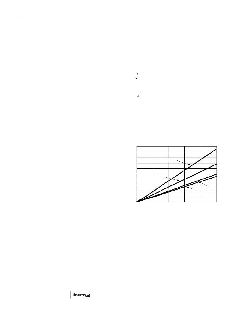
�Depending� on� the� specifics� of� the� input� power� and� its�
�impedance,� most� (or� all)� of� this� current� is� supplied� by� the� input�
�capacitor(s).� Figure� 30� shows� the� advantage� of� having� the� PWM�
�converters� operating� out-of-phase.� If� the� converters� were�
�operating� in� phase,� the� combined� RMS� current� would� be� the�
�algebraic� sum,� which� is� a� much� larger� value� as� shown.� The�
�combined� out-of-phase� current� is� the� square� root� of� the� sum� of�
�the� square� of� the� individual� reflected� currents� and� is� significantly�
�less� than� the� combined� in-phase� current.�
�is� that� the� ‘ESR� zero’� (f� Z� )� be� between� 2kHz� and� 60kHz.� This� range�
�is� set� by� an� internal,� single� compensation� zero� at� 8.8kHz.� The�
�ESR� zero� can� be� a� factor� of� five� on� either� side� of� the� internal� zero�
�and� still� contribute� to� increased� phase� margin� of� the� control� loop.�
�Therefore:�
�5.0�
�4.5�
�4.0�
�3.5�
�3.0�
�IN PHASE�
�C� OUT� =� ----------------------------------�
�1�
�2� π� (� ESR� )� (� f� Z� )�
�(EQ.� 19)�
�2.5�
�2.0�
�OUT-OF-PHASE�
�In� conclusion,� the� output� capacitors� must� meet� three� criteria:�
�1.� They� must� have� sufficient� bulk� capacitance� to� sustain� the�
�output� voltage� during� a� load� transient� while� the� output�
�1.5�
�1.0�
�0.5�
�3.3V�
�5V�
�inductor� current� is� slewing� to� the� value� of� the� load� transient.�
�2.� The� ESR� must� be� sufficiently� low� to� meet� the� desired� output�
�0�
�0�
�1�
�2� 3�
�3.3V� AND� 5V� LOAD� CURRENT�
�4�
�5�
�voltage� ripple� due� to� the� output� inductor� current.�
�3.� The� ESR� zero� should� be� placed,� in� a� rather� large� range,� to�
�provide� additional� phase� margin.�
�The� recommended� output� capacitor� value� for� the� ISL9444� is�
�between� 100μF� to� 680μF,� to� meet� stability� criteria� with� external�
�compensation.� Use� of� aluminum� electrolytic� (POSCAP)� or�
�tantalum� type� capacitors� is� recommended.� Use� of� low� ESR�
�ceramic� capacitors� is� possible� with� loop� analysis� to� ensure�
�stability.�
�22�
�FIGURE� 30.� INPUT� RMS� CURRENT� vs� LOAD�
�Use� a� mix� of� input� bypass� capacitors� to� control� the� voltage� ripple�
�across� the� MOSFETs.� Use� ceramic� capacitors� for� the� high�
�frequency� decoupling� and� bulk� capacitors� to� supply� the� RMS�
�current.� Small� ceramic� capacitors� can� be� placed� very� close� to� the�
�upper� MOSFET� to� suppress� the� voltage� induced� in� the� parasitic�
�circuit� impedances.�
�For� board� designs� that� allow� through-hole� components,� the�
�Sanyo� OS-CON?� series� offer� low� ESR� and� good� temperature�
�performance.� For� surface� mount� designs,� solid� tantalum�
�capacitors� can� be� used,� but� caution� must� be� exercised� with�
�regard� to� the� capacitor� surge� current� rating.� These� capacitors�
�must� be� capable� of� handling� the� surge-current� at� power-up.� The�
�TPS� series� available� from� AVX� is� surge� current� tested.�
�FN7665.3�
�May� 29,� 2012�
�相关PDF资料 |
PDF描述 |
|---|---|
| ISL9491ERZ | IC REG SGL LNB CONTROL 16QFN |
| ISL9492ERZ-T | IC REG SGL LNB CONTROL 28TQFN |
| ISL9506HRZ | IC REG CTRLR BUCK PWM 40-QFN |
| ISL95210IRZ | IC REG BUCK SYNC ADJ 10A 32QFN |
| ISL95870BIRZ | IC CTRLR PWM 1PHASE GPU 20QFN |
相关代理商/技术参数 |
参数描述 |
|---|---|
| ISL9444IRZS2750 | 制造商:Intersil Corporation 功能描述:PB FREE. ISL9444 TRIPLE, STEP- DOWN PWM CONTROLLER IMVP-6. 4 - Rail/Tube |
| ISL9444IRZ-T | 功能描述:IC REG CTRLR BUCK PWM CM 40-QFN RoHS:是 类别:集成电路 (IC) >> PMIC - 稳压器 - DC DC 切换控制器 系列:- 产品培训模块:Lead (SnPb) Finish for COTS Obsolescence Mitigation Program 标准包装:2,500 系列:- PWM 型:电流模式 输出数:1 频率 - 最大:275kHz 占空比:50% 电源电压:18 V ~ 110 V 降压:无 升压:无 回扫:无 反相:无 倍增器:无 除法器:无 Cuk:无 隔离:是 工作温度:-40°C ~ 85°C 封装/外壳:8-SOIC(0.154",3.90mm 宽) 包装:带卷 (TR) |
| ISL9444IRZ-T7A | 功能描述:软开关 PWM 控制器 ISL9444 TRIPLE STEP DWN PWM CONTRLR RoHS:否 制造商:Fairchild Semiconductor 输出端数量: 输出电流: 开关频率: 工作电源电压:30 V 电源电流: 最大工作温度:+ 105 C 最小工作温度:- 40 C 安装风格:SMD/SMT 封装 / 箱体:SOIC-8 封装:Reel |
| ISL9444IRZ-T7AS2750 | 制造商:Intersil Corporation 功能描述:ISL9444 TRIPLE, STEP- DOWN PWM CONTROLLER IMVP-6. 40 LD MLFP - Tape and Reel |
| ISL9444IRZ-TS2750 | 制造商:Intersil Corporation 功能描述:PB FREE. ISL9444 TRIPLE, STEP- DOWN PWM CONTROLLER IMVP-6. 4 - Tape and Reel |
发布紧急采购,3分钟左右您将得到回复。