- 您现在的位置:买卖IC网 > PDF目录79605 > IT80C51-12D (ATMEL CORP) 8-BIT, MROM, 12 MHz, MICROCONTROLLER, PQFP44 PDF资料下载
参数资料
| 型号: | IT80C51-12D |
| 厂商: | ATMEL CORP |
| 元件分类: | 微控制器/微处理器 |
| 英文描述: | 8-BIT, MROM, 12 MHz, MICROCONTROLLER, PQFP44 |
| 封装: | 1 MM HEIGHT, QFP-44 |
| 文件页数: | 104/109页 |
| 文件大小: | 10824K |
| 代理商: | IT80C51-12D |
第1页第2页第3页第4页第5页第6页第7页第8页第9页第10页第11页第12页第13页第14页第15页第16页第17页第18页第19页第20页第21页第22页第23页第24页第25页第26页第27页第28页第29页第30页第31页第32页第33页第34页第35页第36页第37页第38页第39页第40页第41页第42页第43页第44页第45页第46页第47页第48页第49页第50页第51页第52页第53页第54页第55页第56页第57页第58页第59页第60页第61页第62页第63页第64页第65页第66页第67页第68页第69页第70页第71页第72页第73页第74页第75页第76页第77页第78页第79页第80页第81页第82页第83页第84页第85页第86页第87页第88页第89页第90页第91页第92页第93页第94页第95页第96页第97页第98页第99页第100页第101页第102页第103页当前第104页第105页第106页第107页第108页第109页
806
32117D–AVR-01/12
AT32UC3C
The Transmitter can be operated by writing to the Transmitter Holding Register (RHR), when-
ever the Transmit Ready (TXRDY) bit in the Status Register (SR) is set. Successive values
written to THR should correspond to the samples from the left and right audio channels, or from
channels 0 to MR.NBCHAN in TDM mode, for the successive frames.
The Receive Ready and Transmit Ready bits can be polled by reading the Status Register.
The IISC processor load can be reduced by enabling interrupt-driven operation. The RXRDY
and/or TXRDY interrupt requests can be enabled by writing a one to the corresponding bit in the
Interrupt Enable Register (IER). The interrupt service routine associated to the IISC interrupt
request will then be executed whenever the Receive Ready or the Transmit Ready status bit is
set.
30.6.3
Master, Controller, and Slave Modes
In Master and Controller modes, the IISC provides the Master Clock, the Serial Clock and the
Word Select. IMCK, ISCK, and IWS pins are outputs.
In Controller mode, the IISC Receiver and Transmitter are disabled. Only the clocks are enabled
and used by an external receiver and/or transmitter.
In Slave mode, the IISC receives the Serial Clock and the Word Select from an external master.
ISCK and IWS pins are inputs.
The mode is selected by writing the MODE field of the Mode Register (MR). Since the MODE
field changes the direction of the IWS and ISCK pins, the Mode Register should only be written
when the IISC is stopped, in order to avoid unwanted glitches on the IWS and ISCK pins.
30.6.4
I
2S Reception and Transmission Sequence
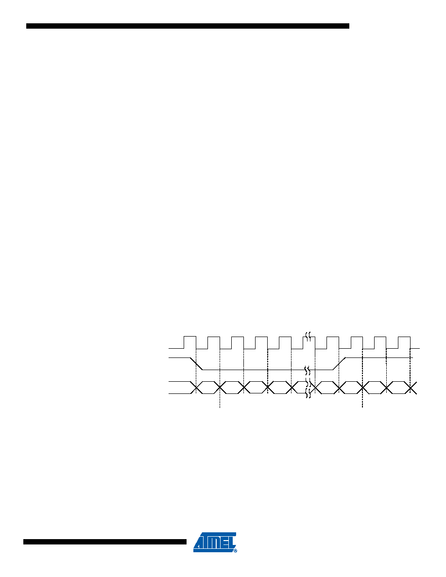
As specified in the I2S protocol, data bits are left-adjusted in the Word Select time slot, with the
MSB transmitted first, starting one clock period after the transition on the Word Select line.
Figure 30-2. I
2S Reception and Transmission Sequence
Data bits are sent on the falling edge of the Serial Clock and sampled on the rising edge of the
Serial Clock. The Word Select line indicates the channel in transmission, a low level for the left
channel and a high level for the right channel.
The length of transmitted words can be chosen among 8, 16, 18, 20, 24, and 32 bits by writing
the MR.DATALENGTH field.
If the time slot allows for more data bits than written in the MR.DATALENGTH field, zeroes are
appended to the transmitted data word or extra received bits are discarded. If the time slot
allows for less data bits than written, the extra bits to be transmitted are not sent or the missing
bits are set to zero in the received data word.
Serial Clock ISCK
Word Select IWS
Data ISDI/ISDO
MSB
Left Channel
LSB
MSB
Right Channel
相关PDF资料 |
PDF描述 |
|---|---|
| IT80C31-25D | 8-BIT, 25 MHz, MICROCONTROLLER, PQFP44 |
| IF280C51C-36R | 8-BIT, MROM, 36 MHz, MICROCONTROLLER, PQFP44 |
| IV80C32-L16R | 8-BIT, 16 MHz, MICROCONTROLLER, PQFP44 |
| IQ80C52TXXX-L16D | 8-BIT, MROM, 16 MHz, MICROCONTROLLER, CQFP44 |
| IR80C52TXXX-20R | 8-BIT, MROM, 20 MHz, MICROCONTROLLER, CQCC44 |
相关代理商/技术参数 |
参数描述 |
|---|---|
| IT80C51-16 | 制造商:未知厂家 制造商全称:未知厂家 功能描述:8-Bit Microcontroller |
| IT80C51-20 | 制造商:未知厂家 制造商全称:未知厂家 功能描述:8-Bit Microcontroller |
| IT80C51-25 | 制造商:未知厂家 制造商全称:未知厂家 功能描述:8-Bit Microcontroller |
| IT80C51-30 | 制造商:未知厂家 制造商全称:未知厂家 功能描述:8-Bit Microcontroller |
| IT80C51-36 | 制造商:未知厂家 制造商全称:未知厂家 功能描述:8-Bit Microcontroller |
发布紧急采购,3分钟左右您将得到回复。