- 您现在的位置:买卖IC网 > PDF目录15745 > KIT908EINTFC (Freescale Semiconductor)KIT EVAL 908E625 QUAD W/MCU/LIN PDF资料下载
参数资料
| 型号: | KIT908EINTFC |
| 厂商: | Freescale Semiconductor |
| 文件页数: | 28/49页 |
| 文件大小: | 0K |
| 描述: | KIT EVAL 908E625 QUAD W/MCU/LIN |
| 标准包装: | 1 |
第1页第2页第3页第4页第5页第6页第7页第8页第9页第10页第11页第12页第13页第14页第15页第16页第17页第18页第19页第20页第21页第22页第23页第24页第25页第26页第27页当前第28页第29页第30页第31页第32页第33页第34页第35页第36页第37页第38页第39页第40页第41页第42页第43页第44页第45页第46页第47页第48页第49页
Analog Integrated Circuit Device Data
34
Freescale Semiconductor
908E625
FUNCTIONAL DEVICE OPERATION
LOGIC COMMANDS AND REGISTERS
H-Bridge Current Limitation Selection Bits (CLS2:CLS0)
These read/write bits select the current limitation value
according to Figure 10. Reset clears the CLS2:CLS0 bits.
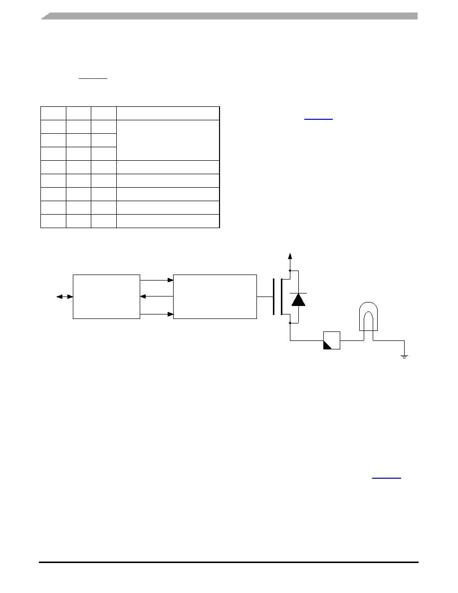
HIGH SIDE DRIVER
The high side output is a low-resistive high side switch
targeted for driving lamps. The high side is protected against
over-temperature. To limit the high inrush current of bulbs,
over-current protection circuitry is used to limit the current.
The output is enabled with bit PSON in the system control
register and can be switched on/off with bit HS_ON in the
power output register. Figure 21 depicts the high-side switch
circuitry and connection to external lamp.
HIGH-SIDE OVER-VOLTAGE/UNDER-VOLTAGE
PROTECTION
The high side output pin, HS, is protected against under-
voltage/over-voltage conditions. This protection is done by
the low and high voltage interrupt circuitry. If one of these
flags (LVF, HVF) is set, the output is disabled.
The over-voltage/under-voltage status flags are cleared
and the output re-enabled by writing a Logic [1] to the LVF/
HVF flags in the interrupt flag register or by reset. Clearing
this flag is useless as long as a high or low voltage condition
is present.
Figure 21. High Side Circuitry
HIGH SIDE OVER-TEMPERATURE PROTECTION
The high side output provides an over-temperature pre-
warning with the HTF in the interrupt flag register. In order to
protect the output against over-temperature, the high-
temperature reset must be enabled. If this value is reached,
the part generates a reset and disables all power outputs.
HIGH-SIDE OVER-CURRENT PROTECTION
The high side output is protected against over-current. In
the event over-current limit is or was reached, the output
automatically switches off and the over-current flag is set.
Due to the high inrush current of bulbs, a special feature of
the 908E625 prevents an over-current shutdown during this
inrush. If an PWM frequency is supplied to the FGEN output
during the switching on of a bulb, the inrush current is limited
to the over-current shutdown limit. This means if the current
reaches the over-current shutdown, the high side will be
switched off, but each rising edge on the FGEN input will
enable the driver again.
To distinguish between a shutdown due to an inrush
current or a real shutdown, the software must check if the
over-current status flag (HS_OCF) in the System Status
Register is set beyond a certain period of time. The over-
current status flag is cleared by writing a Logic [1] to the
HS_OCF in the System Status Register, see Figure 22.
Table 10. H-Bridge Current Limitation Value Selection
Bits
CLS2
CLS1
CLS0
Current Limit
000
No Limit
001
010
011
55 mA (typ)
100
260 mA (typ)
101
370 mA (typ)
110
550 mA (typ)
111
740 mA (typ)
VSUP
HS
High Side Driver
Charge Pump,
OVer-current Protection,
Inrush Current Limiter
Control
On/Off
Current
Limit
Status
相关PDF资料 |
PDF描述 |
|---|---|
| MAX6440UTLQZD7+T | IC BATTERY MON SNGL SOT23-6 |
| UVR2F2R2MPD | CAP ALUM 2.2UF 315V 20% RADIAL |
| MAX6440UTLQYD7+T | IC BATTERY MON SNGL SOT23-6 |
| MAX6440UTKSYD7+T | IC BATTERY MON SNGL SOT23-6 |
| MAX6440UTMRSD3+T | IC BATTERY MON SNGL SOT23-6 |
相关代理商/技术参数 |
参数描述 |
|---|---|
| KIT-910 | 制造商:Anderson Power Products (APP) 功能描述:KIT |
| KIT912F634EVME | 功能描述:开发板和工具包 - S08 / S12 INTEGRATED DUAL L/H SWIT RoHS:否 产品:Development Kits 工具用于评估:MC9S12G128 核心:S12 接口类型:CAN, LIN, RS-232, USB 工作电源电压:5 V 制造商:Freescale Semiconductor |
| KIT912H634EVME | 功能描述:开发板和工具包 - S08 / S12 DUAL LOW&HIDE SWITCH EVB RoHS:否 产品:Development Kits 工具用于评估:MC9S12G128 核心:S12 接口类型:CAN, LIN, RS-232, USB 工作电源电压:5 V 制造商:Freescale Semiconductor |
| KIT912J637EVME | 功能描述:电源管理IC开发工具 BATTERY SENSOR 912J637 RoHS:否 制造商:Maxim Integrated 产品:Evaluation Kits 类型:Battery Management 工具用于评估:MAX17710GB 输入电压: 输出电压:1.8 V |
| KIT912S812ECUEVM | 功能描述:电源管理IC开发工具 Single Cylinder S12XS E RoHS:否 制造商:Maxim Integrated 产品:Evaluation Kits 类型:Battery Management 工具用于评估:MAX17710GB 输入电压: 输出电压:1.8 V |
发布紧急采购,3分钟左右您将得到回复。