- 您现在的位置:买卖IC网 > PDF目录80167 > L99PM62XPTR (STMICROELECTRONICS) 4-CHANNEL POWER SUPPLY MANAGEMENT CKT, PDSO36 PDF资料下载
参数资料
| 型号: | L99PM62XPTR |
| 厂商: | STMICROELECTRONICS |
| 元件分类: | 电源管理 |
| 英文描述: | 4-CHANNEL POWER SUPPLY MANAGEMENT CKT, PDSO36 |
| 封装: | ROHS COMPLIANT, POWERSSO-36 |
| 文件页数: | 9/98页 |
| 文件大小: | 1117K |
| 代理商: | L99PM62XPTR |
第1页第2页第3页第4页第5页第6页第7页第8页当前第9页第10页第11页第12页第13页第14页第15页第16页第17页第18页第19页第20页第21页第22页第23页第24页第25页第26页第27页第28页第29页第30页第31页第32页第33页第34页第35页第36页第37页第38页第39页第40页第41页第42页第43页第44页第45页第46页第47页第48页第49页第50页第51页第52页第53页第54页第55页第56页第57页第58页第59页第60页第61页第62页第63页第64页第65页第66页第67页第68页第69页第70页第71页第72页第73页第74页第75页第76页第77页第78页第79页第80页第81页第82页第83页第84页第85页第86页第87页第88页第89页第90页第91页第92页第93页第94页第95页第96页第97页第98页
L99PM62XP
Description
Doc ID 16363 Rev 2
Note:
Inputs TxDL, TxDC and CSN must be at high level or at high impedance in order to achieve
minimum standby current in V1 standby mode.
Inputs DI and CLK must be at GND or at high impedance to achieve minimum standby
current in V1 standby mode.
Interrupt
The interrupt signal (linked to RxDL/NINT internally) indicates a wake-up event from V1
standby mode. In case of a wake-up by Wake-up Inputs, activity on LIN or CAN, SPI access
or timer-interrupt the NINT pin is pulled low for 56 s.
In case of V1 standby mode and (IV1 > Icmp), the device remains in standby mode, the V1
regulator switches to high current mode and the watchdog starts. No Interrupt signal is
generated.
2.2.4
VBAT standby mode
The transition from active mode to VBAT standby mode is initiated by an SPI command.
In VBAT standby mode, the V1 voltage regulator, relay outputs, LIN and CAN transmitters are
switched off. High-side outputs and the V2 regulator remain in the configuration
programmed prior to the standby command.
In VBAT standby mode the current consumption of the L99PM62XP is reduced to a minimum
level.
Note:
Inputs TXDL, TXDC and CSN must be terminated to GND in VBAT standby to achieve
minimum standby current.
This can be achieved with the internal ESD protection diodes of the microcontroller
(microcontroller is not supplied in this mode; V1 is pulled to GND).
2.2.5
Wake up from standby modes
A wake-up from standby mode switches the device to active mode. This can be initiated by
one or more of the following events:
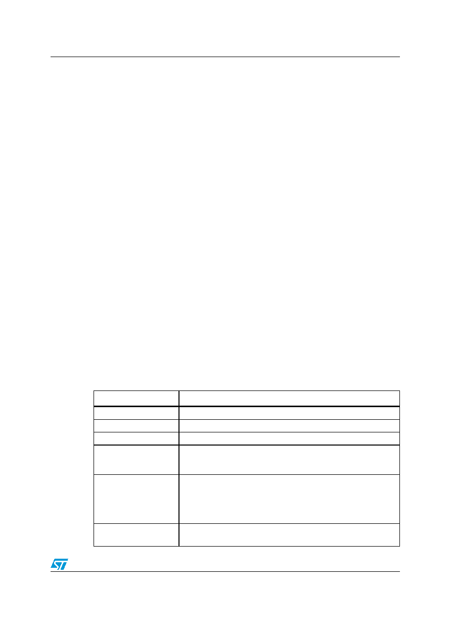
Table 3.
Wake up sources
Wake up source
Description
LIN bus activity
Can be disabled by SPI
CAN bus activity
Can be disabled by SPI
Level change of WU1 - 3
Can be individually configured or disabled by SPI
IV1 > Icmp
Device remains in V1 standby mode but watchdog is enabled (If
Icmp = 0) and the V1 regulator goes into high current mode (increased
current consumption). No interrupt is generated.
Timer interrupt / wake up
of C by TIMER
Programmable by SPI
–V1 standby mode: device wakes up and Interrupt signal is generated
at RxDL/NINT when programmable timeout has elapsed
–VBAT standby mode: device wakes up, V1 regulator is turned on and
NReset signal is generated when programmable timeout has elapsed
SPI access
Always active (except in VBAT standby mode)
Wake up event: CSN is low and first rising edge on CLK
相关PDF资料 |
PDF描述 |
|---|---|
| LSN-1.8/10-D3J | 1-OUTPUT DC-DC REG PWR SUPPLY MODULE |
| LSN-1.25/10-D3B | 1-OUTPUT DC-DC REG PWR SUPPLY MODULE |
| LS4601-7EPD7TB1 | 1-OUTPUT 100 W AC-DC PWR FACTOR CORR MODULE |
| LS5540-7ERD9TB1 | 2-OUTPUT 100 W AC-DC PWR FACTOR CORR MODULE |
| LS5540-7ERD5TB1 | 2-OUTPUT 100 W AC-DC PWR FACTOR CORR MODULE |
相关代理商/技术参数 |
参数描述 |
|---|---|
| L99PM72GXPTR | 功能描述:Automotive PMIC PowerSSO-36 制造商:stmicroelectronics 系列:- 包装:剪切带(CT) 零件状态:有效 应用:汽车级 电流 - 电源:6mA 电压 - 电源:6 V ~ 18 V 工作温度:-40°C ~ 130°C 安装类型:表面贴装 封装/外壳:36-??FSOP(0.295",7.50mm 宽) 供应商器件封装:PowerSSO-36 标准包装:1 |
| L99SD01-E | 制造商:STMicroelectronics 功能描述:ABD VIPOWER - Rail/Tube |
| L99SD01TR-E | 制造商:STMicroelectronics 功能描述:ABD VIPOWER - Tape and Reel |
| L9A0212 | 制造商:LSI 制造商全称:LSI 功能描述:Microprocessor |
| L9D112G80BG4 | 制造商:LOGIC 制造商全称:LOGIC 功能描述:1.2 Gb, DDR - SDRAM Integrated Module |
发布紧急采购,3分钟左右您将得到回复。