- 您现在的位置:买卖IC网 > PDF目录80315 > LM2596-3.3MWC (NATIONAL SEMICONDUCTOR CORP) 7.5 A SWITCHING REGULATOR, 173 kHz SWITCHING FREQ-MAX, UUC PDF资料下载
参数资料
| 型号: | LM2596-3.3MWC |
| 厂商: | NATIONAL SEMICONDUCTOR CORP |
| 元件分类: | 稳压器 |
| 英文描述: | 7.5 A SWITCHING REGULATOR, 173 kHz SWITCHING FREQ-MAX, UUC |
| 封装: | WAFER |
| 文件页数: | 11/36页 |
| 文件大小: | 827K |
| 代理商: | LM2596-3.3MWC |
第1页第2页第3页第4页第5页第6页第7页第8页第9页第10页当前第11页第12页第13页第14页第15页第16页第17页第18页第19页第20页第21页第22页第23页第24页第25页第26页第27页第28页第29页第30页第31页第32页第33页第34页第35页第36页
Application Information
PIN FUNCTIONS
+V
IN — This is the positive input supply for the IC switching
regulator. A suitable input bypass capacitor must be present
at this pin to minimize voltage transients and to supply the
switching currents needed by the regulator.
Ground — Circuit ground.
Output — Internal switch. The voltage at this pin switches
between (+V
IN VSAT) and approximately 0.5V, with a duty
cycle of approximately V
OUT/VIN. To minimize coupling to
sensitive circuitry, the PC board copper area connected to
this pin should be kept to a minimum.
Feedback — Senses the regulated output voltage to com-
plete the feedback loop.
ON /OFF — Allows the switching regulator circuit to be shut
down using logic level signals thus dropping the total input
supply current to approximately 80 A. Pulling this pin below
a threshold voltage of approximately 1.3V turns the regulator
on, and pulling this pin above 1.3V (up to a maximum of 25V)
shuts the regulator down. If this shutdown feature is not
needed, the ON /OFF pin can be wired to the ground pin or
it can be left open, in either case the regulator will be in the
ON condition.
EXTERNAL COMPONENTS
INPUT CAPACITOR
C
IN — A low ESR aluminum or tantalum bypass capacitor is
needed between the input pin and ground pin. It must be
located near the regulator using short leads. This capacitor
prevents large voltage transients from appearing at the in-
put, and provides the instantaneous current needed each
time the switch turns on.
The important parameters for the Input capacitor are the
voltage rating and the RMS current rating. Because of the
relatively high RMS currents flowing in a buck regulator’s
input capacitor, this capacitor should be chosen for its RMS
current rating rather than its capacitance or voltage ratings,
although the capacitance value and voltage rating are di-
rectly related to the RMS current rating.
The RMS current rating of a capacitor could be viewed as a
capacitor’s power rating. The RMS current flowing through
the capacitors internal ESR produces power which causes
the internal temperature of the capacitor to rise. The RMS
current rating of a capacitor is determined by the amount of
current required to raise the internal temperature approxi-
mately 10C above an ambient temperature of 105C. The
ability of the capacitor to dissipate this heat to the surround-
ing air will determine the amount of current the capacitor can
safely sustain. Capacitors that are physically large and have
a large surface area will typically have higher RMS current
ratings. For a given capacitor value, a higher voltage elec-
trolytic capacitor will be physically larger than a lower voltage
capacitor, and thus be able to dissipate more heat to the
surrounding air, and therefore will have a higher RMS cur-
rent rating.
The consequences of operating an electrolytic capacitor
above the RMS current rating is a shortened operating life.
The higher temperature speeds up the evaporation of the
capacitor’s electrolyte, resulting in eventual failure.
Selecting an input capacitor requires consulting the manu-
facturers data sheet for maximum allowable RMS ripple
current. For a maximum ambient temperature of 40C, a
general guideline would be to select a capacitor with a ripple
current rating of approximately 50% of the DC load current.
For ambient temperatures up to 70C, a current rating of
75% of the DC load current would be a good choice for a
conservative design. The capacitor voltage rating must be at
least 1.25 times greater than the maximum input voltage,
and often a much higher voltage capacitor is needed to
satisfy the RMS current requirements.
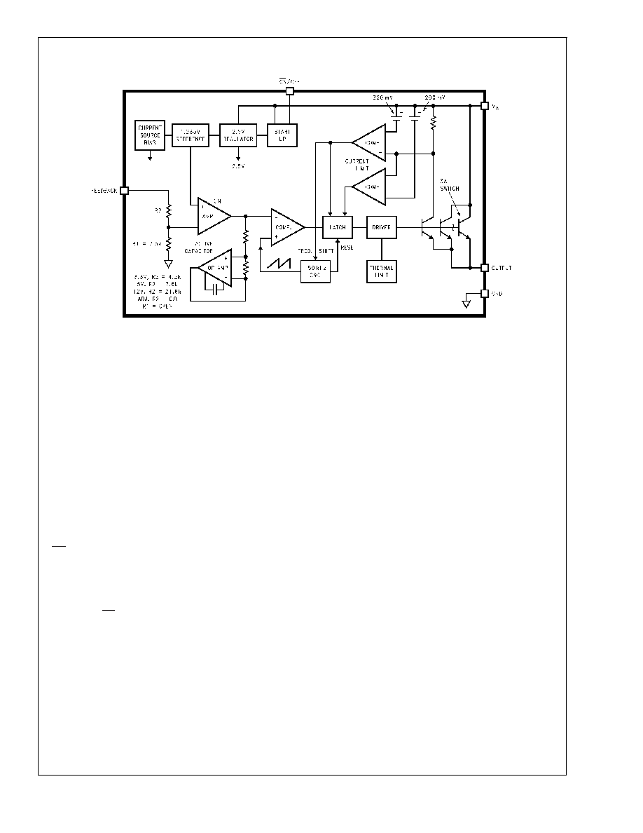
Block Diagram
01258321
FIGURE 12.
LM2596
www.national.com
19
相关PDF资料 |
PDF描述 |
|---|---|
| LM4120AI5.0MWC | 1-OUTPUT THREE TERM VOLTAGE REFERENCE, 5 V, UUC |
| LQS100A48-1V2A | 1-OUTPUT 120 W DC-DC REG PWR SUPPLY MODULE |
| LEN-0.8/28-D12M | 1-OUTPUT 0.25 W DC-DC REG PWR SUPPLY MODULE |
| LEN-1/28-D12 | 1-OUTPUT 0.25 W DC-DC REG PWR SUPPLY MODULE |
| LEN-2/28-D12 | 1-OUTPUT 0.25 W DC-DC REG PWR SUPPLY MODULE |
相关代理商/技术参数 |
参数描述 |
|---|---|
| LM2596ADPBCKGEVB | 功能描述:BOARD EVAL LM2596ADJ BUCK D2PAK RoHS:是 类别:编程器,开发系统 >> 评估板 - DC/DC 与 AC/DC(离线)SMPS 系列:* 产品培训模块:Obsolescence Mitigation Program 标准包装:1 系列:True Shutdown™ 主要目的:DC/DC,步升 输出及类型:1,非隔离 功率 - 输出:- 输出电压:- 电流 - 输出:1A 输入电压:2.5 V ~ 5.5 V 稳压器拓扑结构:升压 频率 - 开关:3MHz 板类型:完全填充 已供物品:板 已用 IC / 零件:MAX8969 |
| LM2596ATPBCKGEVB | 功能描述:BOARD EVAL LM2596ADJ BUCK TO-220 RoHS:是 类别:编程器,开发系统 >> 评估板 - DC/DC 与 AC/DC(离线)SMPS 系列:* 产品培训模块:Obsolescence Mitigation Program 标准包装:1 系列:True Shutdown™ 主要目的:DC/DC,步升 输出及类型:1,非隔离 功率 - 输出:- 输出电压:- 电流 - 输出:1A 输入电压:2.5 V ~ 5.5 V 稳压器拓扑结构:升压 频率 - 开关:3MHz 板类型:完全填充 已供物品:板 已用 IC / 零件:MAX8969 |
| LM2596DSADJG | 功能描述:直流/直流开关调节器 3A BUCK SWCH 150KHZ RoHS:否 制造商:International Rectifier 最大输入电压:21 V 开关频率:1.5 MHz 输出电压:0.5 V to 0.86 V 输出电流:4 A 输出端数量: 最大工作温度: 安装风格:SMD/SMT 封装 / 箱体:PQFN 4 x 5 |
| LM2596DSADJR4G | 功能描述:直流/直流开关调节器 3A BUCK SWCH 150KHZ RoHS:否 制造商:International Rectifier 最大输入电压:21 V 开关频率:1.5 MHz 输出电压:0.5 V to 0.86 V 输出电流:4 A 输出端数量: 最大工作温度: 安装风格:SMD/SMT 封装 / 箱体:PQFN 4 x 5 |
| LM2596S | 制造商:Texas Instruments 功能描述: |
发布紧急采购,3分钟左右您将得到回复。