- 您现在的位置:买卖IC网 > PDF目录2082 > LMH6734MQX/NOPB (National Semiconductor)IC BUFFER TRPL SELECT 16-SSOP PDF资料下载
参数资料
| 型号: | LMH6734MQX/NOPB |
| 厂商: | National Semiconductor |
| 文件页数: | 12/21页 |
| 文件大小: | 0K |
| 描述: | IC BUFFER TRPL SELECT 16-SSOP |
| 标准包装: | 2,500 |
| 系列: | PowerWise® |
| 应用: | 电流反馈 |
| 电路数: | 3 |
| -3db带宽: | 925MHz |
| 转换速率: | 3750 V/µs |
| 电流 - 电源: | 19.5mA |
| 电流 - 输出 / 通道: | 80mA |
| 电压 - 电源,单路/双路(±): | 3 V ~ 12 V,±1.5 V ~ 6 V |
| 安装类型: | 表面贴装 |
| 封装/外壳: | 16-LSSOP(0.154",3.90mm 宽) |
| 供应商设备封装: | 16-QSOP |
| 包装: | 带卷 (TR) |
| 配用: | LMH730275/NOPB-ND - EVAL BOARD HS TRIPLE SSOP OPAMP |
| 其它名称: | LMH6734MQX |
OBSOLETE
SNOSAY0C – JUNE 2007 – REVISED APRIL 2013
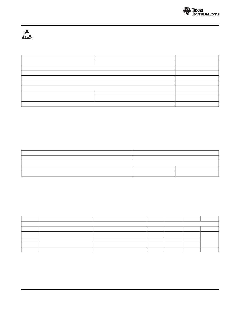
These devices have limited built-in ESD protection. The leads should be shorted together or the device placed in conductive foam
during storage or handling to prevent electrostatic damage to the MOS gates.
Absolute Maximum Ratings
(1) (2)
ESD Tolerance(3)
Human Body Model
2000V
Machine Model
200V
Supply Voltage (V+ - V–)
13.2V
IOUT
See(4)
Common Mode Input Voltage
±VCC
Maximum Junction Temperature
+150°C
Storage Temperature Range
65°C to +150°C
Soldering Information
Infrared or Convection (20 sec.)
235°C
Wave Soldering (10 sec.)
260°C
Storage Temperature Range
65°C to +150°C
(1)
Absolute Maximum Ratings indicate limits beyond which damage to the device may occur. Operating Ratings indicate conditions for
which the device is intended to be functional, but specific performance is not ensured. For ensured specifications, see the Electrical
Characteristics tables.
(2)
If Military/Aerospace specified devices are required, please contact the Texas Instruments Sales Office/ Distributors for availability and
specifications.
(3)
Human Body Model, applicable std. MIL-STD-883, Method 3015.7. Machine Model, applicable std. JESD22-A115-A (ESD MM std. of
JEDECField-Induced Charge-Device Model, applicable std. JESD22-C101-C (ESD FICDM std. of JEDEC).
(4)
The maximum output current (IOUT) is determined by device power dissipation limitations. See the POWER DISSIPATION section of the
Application Information for more details.
Operating Ratings
(1)
Temperature Range(2)
40°C to +85°C
Supply Voltage (V+ - V–)
3V to 12V
Thermal Resistance
Package
(
θJC)
(
θJA)
16-Pin SSOP
36°C/W
120°C/W
(1)
Absolute Maximum Ratings indicate limits beyond which damage to the device may occur. Operating Ratings indicate conditions for
which the device is intended to be functional, but specific performance is not ensured. For ensured specifications, see the Electrical
Characteristics tables.
(2)
The maximum power dissipation is a function of TJ(MAX), θJA. The maximum allowable power dissipation at any ambient temperature is
PD = (TJ(MAX) - TA) / θJA. All numbers apply for packages soldered directly onto a PC Board.
5V Electrical Characteristics
(1)
Unless otherwise specified, all limits are ensured for TA = 25°C, V
+ = +5V, A
V = +2, RL = 100. Boldface limits apply at the
temperature extremes.
Symbol
Parameter
Conditions
Min(2)
Typ(3)
Max(2)
Units
Frequency Domain Performance
UGBW
3 dB Bandwidth
Unity Gain, VOUT = 200 mVPP
870
MHz
SSBW
3 dB Bandwidth
VOUT = 200 mVPP, RL = 100
650
SSBW
VOUT = 200 mVPP, RL = 150
685
MHz
LSBW
VOUT = 2 VPP
480
0.1 dB BW 0.1 dB Gain Flatness
VOUT = 200 mVPP
130
MHz
(1)
Electrical Table values apply only for factory testing conditions at the temperature indicated. Factory testing conditions result in very
limited self-heating of the device such that TJ = TA. No guarantee of parametric performance is indicated in the electrical tables under
conditions of internal self heating where TJ> TA. See Application Information for information on temperature de-rating of this device.
Min/Max ratings are based on product characterization and simulation. Individual parameters are tested as noted.
(2)
Limits are 100% production tested at 25C. Limits over the operating temperature range are specified through correlation using Statistical
Quality Control (SQC) methods.
(3)
Typical values represent the most likely parametric norm as determined at the time of characterization. Actual typical values may vary
over time and will also depend on the application and configuration. The typical values are not tested and are not specified on shipped
production material.
2
Copyright 2007–2013, Texas Instruments Incorporated
Product Folder Links: LMH6734
相关PDF资料 |
PDF描述 |
|---|---|
| LMK04010BISQ/NOPB | IC CLOCK CONDITIONER W/PLL 48LLP |
| LMV393MUTAG | IC OP AMP DUAL GP LV LV 8-UDFN |
| LMX339HASD+T | IC COMPARATOR GP QUAD 14-SOIC |
| LT1011AIS8#TRPBF | IC VOLTAGE COMPARATOR 5V 8-SOIC |
| LT1016IS8#TRPBF | IC COMPARATOR 10NS HI-SPD 8-SOIC |
相关代理商/技术参数 |
参数描述 |
|---|---|
| LMH6738 | 制造商:NSC 制造商全称:National Semiconductor 功能描述:Very Wideband, Low Distortion Triple Op Amp |
| LMH6738MQ | 功能描述:运算放大器 - 运放 RoHS:否 制造商:STMicroelectronics 通道数量:4 共模抑制比(最小值):63 dB 输入补偿电压:1 mV 输入偏流(最大值):10 pA 工作电源电压:2.7 V to 5.5 V 安装风格:SMD/SMT 封装 / 箱体:QFN-16 转换速度:0.89 V/us 关闭:No 输出电流:55 mA 最大工作温度:+ 125 C 封装:Reel |
| LMH6738MQ/NOPB | 功能描述:运算放大器 - 运放 Triple Video Op-Amp RoHS:否 制造商:STMicroelectronics 通道数量:4 共模抑制比(最小值):63 dB 输入补偿电压:1 mV 输入偏流(最大值):10 pA 工作电源电压:2.7 V to 5.5 V 安装风格:SMD/SMT 封装 / 箱体:QFN-16 转换速度:0.89 V/us 关闭:No 输出电流:55 mA 最大工作温度:+ 125 C 封装:Reel |
| LMH6738MQX | 功能描述:运算放大器 - 运放 RoHS:否 制造商:STMicroelectronics 通道数量:4 共模抑制比(最小值):63 dB 输入补偿电压:1 mV 输入偏流(最大值):10 pA 工作电源电压:2.7 V to 5.5 V 安装风格:SMD/SMT 封装 / 箱体:QFN-16 转换速度:0.89 V/us 关闭:No 输出电流:55 mA 最大工作温度:+ 125 C 封装:Reel |
| LMH6738MQX/NOPB | 功能描述:运算放大器 - 运放 RoHS:否 制造商:STMicroelectronics 通道数量:4 共模抑制比(最小值):63 dB 输入补偿电压:1 mV 输入偏流(最大值):10 pA 工作电源电压:2.7 V to 5.5 V 安装风格:SMD/SMT 封装 / 箱体:QFN-16 转换速度:0.89 V/us 关闭:No 输出电流:55 mA 最大工作温度:+ 125 C 封装:Reel |
发布紧急采购,3分钟左右您将得到回复。