- 您现在的位置:买卖IC网 > PDF目录16329 > LMK04031BEVAL/NOPB (National Semiconductor)EVAL BOARD LMK04031BISQ PDF资料下载
参数资料
| 型号: | LMK04031BEVAL/NOPB |
| 厂商: | National Semiconductor |
| 文件页数: | 2/65页 |
| 文件大小: | 0K |
| 描述: | EVAL BOARD LMK04031BISQ |
| 标准包装: | 1 |
| 系列: | PowerWise® |
| 主要目的: | 计时,多用途 |
| 嵌入式: | 否 |
| 已用 IC / 零件: | LMK04031 |
| 已供物品: | 板,线缆,文档,软件 |
第1页当前第2页第3页第4页第5页第6页第7页第8页第9页第10页第11页第12页第13页第14页第15页第16页第17页第18页第19页第20页第21页第22页第23页第24页第25页第26页第27页第28页第29页第30页第31页第32页第33页第34页第35页第36页第37页第38页第39页第40页第41页第42页第43页第44页第45页第46页第47页第48页第49页第50页第51页第52页第53页第54页第55页第56页第57页第58页第59页第60页第61页第62页第63页第64页第65页
SNOSAZ8J – SEPTEMBER 2008 – REVISED SEPTEMBER 2011
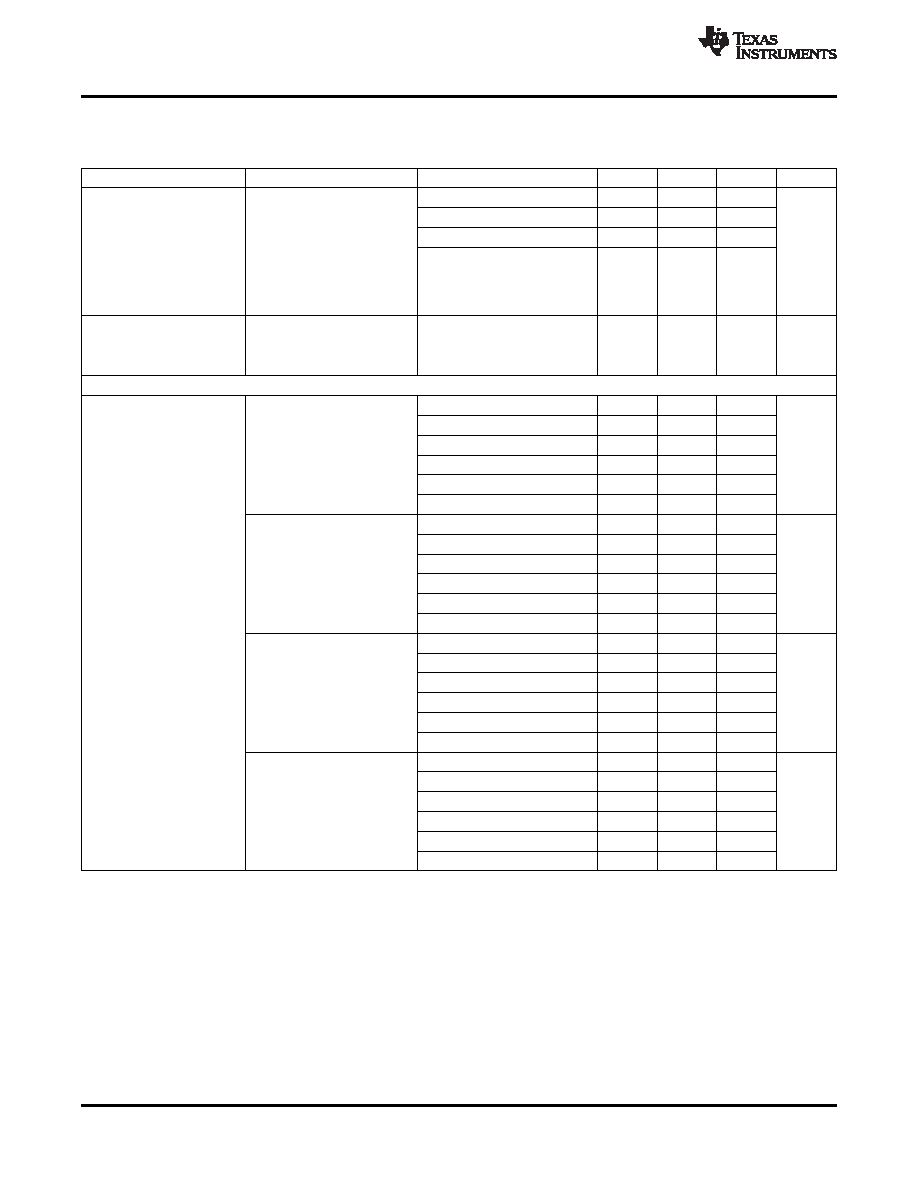
Electrical Characteristics (continued)
(3.15 V
≤ VCC ≤ 3.45 V, -40 °C ≤ TA ≤ 85 °C. Typical values represent most likely parametric norms at VCC = 3.3 V, TA = 25
°C, at the Recommended Operating Conditions at the time of product characterization and are not guaranteed.)
Symbol
Parameter
Conditions
Min
Typ
Max
Units
Fine Tuning Sensitivity
LMK040x0
7 to 9
(The range displayed in the
LMK040x1
8 to 11
typical column indicates the
LMK040x2
9 to 14
lower sensitivity is typical at
KVCO
the lower end of the tuning
MHz/V
range, and the higher tuning
sensitivity is typical at the
LMK040x3
14 to 26
higher end of the tuning
range).
After programming R15 for
Allowable Temperature Drift
lock, no changes to output
|
ΔTCL|
for Continuous Lock
125
°C
configuration are permitted to
(12)
guarantee continuous lock
Internal VCO Open Loop Phase Noise and Jitter
Offset = 1 kHz
-66
Offset = 10 kHz
-94
LMK040x0
fVCO = 1185 MHz
Offset = 100 kHz
-119
SSB Phase Noise
dBc/Hz
Offset = 1 MHz
-139
PLL2 = Open Loop
Measured at Fout
Offset = 10 MHz
-158
Offset = 20 MHz
-163
Offset = 1 kHz
-64
Offset = 10 kHz
-91
LMK040x0
fVCO = 1296 MHz
Offset = 100 kHz
-117
SSB Phase Noise
dBc/Hz
Offset = 1 MHz
-138
PLL2 = Open Loop
Measured at Fout
Offset = 10 MHz
-157
Offset = 20 MHz
-161
L(f)Fout
Offset = 1 kHz
-61
Offset = 10 kHz
-91
LMK040x1
fVCO = 1440 MHz
Offset = 100 kHz
-117
SSB Phase Noise
dBc/Hz
Offset = 1 MHz
-138
PLL2 = Open Loop
Measured at Fout
Offset = 10 MHz
-158
Offset = 20 MHz
-160
Offset = 1 kHz
-58
Offset = 10 kHz
-89
LMK040x1
fVCO = 1560 MHz
Offset = 100 kHz
-115
SSB Phase Noise
dBc/Hz
Offset = 1 MHz
-137
PLL2 = Open Loop
Measured at Fout
Offset = 10 MHz
-157
Offset = 20 MHz
-162
(12) Maximum Allowable Temperature Drift for Continuous Lock is how far the temperature can drift in either direction from the value it was
at the time that the R0 register was last programmed, and still have the part stay in lock. The action of programming the R0 register,
even to the same value, activates a frequency calibration routine. This implies the part will work over the entire frequency range, but if
the temperature drifts more than the maximum allowable drift for continuous lock, then it will be necessary to reload the R0 register to
ensure it stays in lock. Regardless of what temperature the part was initially programmed at, the temperature can never drift outside the
frequency range of -40 °C to 85 °C without violating specifications.
10
Copyright 2008–2011, Texas Instruments Incorporated
相关PDF资料 |
PDF描述 |
|---|---|
| LTC2903CS6-D1#TRMPBF | IC QUAD SPLY MONITOR ADJ SOT23-6 |
| 3-1906054-1 | CA 2MM OFNR 62.5/125,LC SEC GRE |
| PCV1V820MCL1GS | CAP ALUM 82UF 35V 20% SMD |
| 3-1906053-1 | CA 2MM OFNR 62.5/125,LC SEC YEL |
| LMK04033BEVAL/NOPB | BOARD EVALUATION LMK04033 |
相关代理商/技术参数 |
参数描述 |
|---|---|
| LMK04031BEVALXO | 功能描述:时钟和定时器开发工具 LMK04031 EVAL BOARD RoHS:否 制造商:Texas Instruments 产品:Evaluation Modules 类型:Clock Conditioners 工具用于评估:LMK04100B 频率:122.8 MHz 工作电源电压:3.3 V |
| LMK04031BISQ | 制造商:Texas Instruments 功能描述:Clock Conditioner 48-Pin LLP EP T/R |
| LMK04031BISQ/NOPB | 功能描述:时钟合成器/抖动清除器 RoHS:否 制造商:Skyworks Solutions, Inc. 输出端数量: 输出电平: 最大输出频率: 输入电平: 最大输入频率:6.1 GHz 电源电压-最大:3.3 V 电源电压-最小:2.7 V 封装 / 箱体:TSSOP-28 封装:Reel |
| LMK04031BISQE | 制造商:Texas Instruments 功能描述:PRECISION CLOCK CONDITIONER, 48LLP |
| LMK04031BISQE/NOPB | 功能描述:时钟合成器/抖动清除器 RoHS:否 制造商:Skyworks Solutions, Inc. 输出端数量: 输出电平: 最大输出频率: 输入电平: 最大输入频率:6.1 GHz 电源电压-最大:3.3 V 电源电压-最小:2.7 V 封装 / 箱体:TSSOP-28 封装:Reel |
发布紧急采购,3分钟左右您将得到回复。