- 您现在的位置:买卖IC网 > PDF目录20625 > LT1939EDD#PBF (Linear Technology)IC REG DL BUCK/LINEAR 12DFN PDF资料下载
参数资料
| 型号: | LT1939EDD#PBF |
| 厂商: | Linear Technology |
| 文件页数: | 13/24页 |
| 文件大小: | 349K |
| 描述: | IC REG DL BUCK/LINEAR 12DFN |
| 标准包装: | 121 |
| 拓扑: | 降压(降压)(1),线性(LDO)(1) |
| 功能: | 任何功能 |
| 输出数: | 2 |
| 频率 - 开关: | 500kHz ~ 2.4MHz |
| 电压/电流 - 输出 1: | 0.8 V ~ 24.25 V,2A |
| 电压/电流 - 输出 2: | 0.8 V ~ 24.25 V,1A |
| 带 LED 驱动器: | 无 |
| 带监控器: | 无 |
| 带序列发生器: | 无 |
| 电源电压: | 3 V ~ 25 V |
| 工作温度: | -40°C ~ 125°C |
| 安装类型: | 表面贴装 |
| 封装/外壳: | 12-WFDFN 裸露焊盘 |
| 供应商设备封装: | 12-DFN |
| 包装: | 管件 |
LT1939
13
1939f
APPLICATIONS INFORMATION
Discontinuous operation occurs when I
OUT
is less than
I
L
/2 as calculated above.
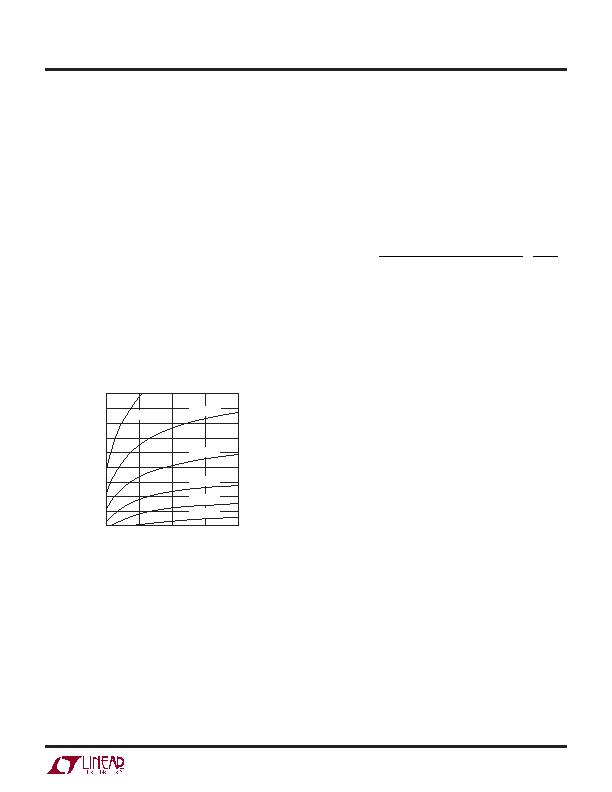
Figure 4 illustrates the inductance value needed for a 3.3V
output with a maximum load capability of 2A. Referring
to Figure 4, an inductor value between 3.3糎 and 4.7糎
will be suf cient for a 15V input voltage and a switch
frequency of 750kHz. There are several graphs in the
Typical Performance Characteristics section of this data
sheet that show inductor selection as a function of input
voltage and switch frequency for several popular output
voltages and output ripple currents. Also, low inductance
may result in discontinuous mode operation, which is
okay, but further reduces maximum load current. For
details of maximum output current and discontinuous
mode operation, see Linear Technology Application Note
44. Finally, for duty cycles greater than 50% (V
OUT
/V
IN
> 0.5), there is a minimum inductance required to avoid
subharmonic oscillations. See Application Note 19 for
more information.
capacitor is required to reduce the resulting voltage
ripple at the LT1939 and to force this very high frequency
switching current into a tight local loop, minimizing EMI.
The input capacitor must have low impedance at the
switching frequency to do this effectively, and it must
have an adequate ripple current rating.
A conservative value is the RMS input current is given
by:
I
CIN(RMS)
=
I
OUT1
V
OUT1
" V
IN
V
OUT1
(
)
0.5
V
I
N
<
I
OUT1
2
and is largest when V
IN
= 2V
OUT1
(50% duty cycle).
The frequency, V
IN
to V
OUT
ratio, and maximum load
current requirement of the LT1939 along with the input
supply source impedance, determine the energy storage
requirements of the input capacitor. Determine the worst-
case condition for input ripple current and then size the
input capacitor such that it reduces input voltage ripple to
an acceptable level. Typical values for input capacitors run
from 10糉 at low frequencies to 2.2糉 at higher frequencies.
The combination of small size and low impedance (low
equivalent series resistance or ESR) of ceramic capacitors
make them the preferred choice. The low ESR results in
very low voltage ripple and the capacitors can handle plenty
of ripple current. They are also comparatively robust and
can be used in this application at their rated voltage. X5R
and X7R types are stable over temperature and applied
voltage, and give dependable service. Other types (Y5V and
Z5U) have very large temperature and voltage coef cients
of capacitance, so they may have only a small fraction of
their nominal capacitance in your application. While they
will still handle the RMS ripple current, the input voltage
ripple may become fairly large, and the ripple current may
end up owing from your input supply or from other by-
pass capacitors in your system, as opposed to being fully
sourced from the local input capacitor. An alternative to a
high value ceramic capacitor is a lower value along with
a larger electrolytic capacitor, for example a 1糉 ceramic
capacitor in parallel with a low ESR tantalum capacitor.
For the electrolytic capacitor, a value larger than 10糉 will
be required to meet the ESR and ripple current require-
ments. Because the input capacitor is likely to see high
Figure 4. Inductor Values for 2A Maximum Load Current
(V
OUT1
= 3.3V, I
RIPPLE
= 1A)
Input Capacitor Selection
Bypass the input of the LT1939 circuit with a 4.7糉 or
higher ceramic capacitor of X7R or X5R type. A lower
value or a less expensive Y5V type can be used if there
is additional bypassing provided by bulk electrolytic or
tantalum capacitors. The following paragraphs describe
the input capacitor considerations in more detail.
Step-down regulators draw current from the input sup-
ply in pulses with very fast rise and fall times. The input
INPUT VOLTAGE (V)
5
250
500
1000
1250
1500
2500
1939 F04
750
15
10
20
25
1750
2000
2250
L = 1糎
L = 1.5糎
L = 2.2糎
L = 3.3糎
L = 4.7糎
L = 6.8糎
相关PDF资料 |
PDF描述 |
|---|---|
| T95Y685M025LZAL | CAP TANT 6.8UF 25V 20% 2910 |
| V48C12H75BG2 | CONVERTER MOD DC/DC 12V 75W |
| ISL6612ACBZAR5214 | IC MOSFET DRVR SYNC BUCK 8-SOIC |
| CS5463-ISZR | IC ENERGY METERING 1PHASE 24SSOP |
| 591D227X9010R2T20H | CAP TANT 220UF 10V 10% 2824 |
相关代理商/技术参数 |
参数描述 |
|---|---|
| LT1939EDD-TRPBF | 制造商:LINER 制造商全称:Linear Technology 功能描述:Monolithic 2A Step-Down Regulator Plus Linear Regulator/Controller |
| LT1939IDD#PBF | 功能描述:IC REG DL BUCK/LINEAR 12DFN RoHS:是 类别:集成电路 (IC) >> PMIC - 稳压器 - 线性 + 切换式 系列:- 标准包装:2,500 系列:- 拓扑:降压(降压)同步(3),线性(LDO)(2) 功能:任何功能 输出数:5 频率 - 开关:300kHz 电压/电流 - 输出 1:控制器 电压/电流 - 输出 2:控制器 电压/电流 - 输出 3:控制器 带 LED 驱动器:无 带监控器:无 带序列发生器:是 电源电压:5.6 V ~ 24 V 工作温度:-40°C ~ 85°C 安装类型:* 封装/外壳:* 供应商设备封装:* 包装:* |
| LT1939IDD#TRPBF | 功能描述:IC REG DL BUCK/LINEAR 12DFN RoHS:是 类别:集成电路 (IC) >> PMIC - 稳压器 - 线性 + 切换式 系列:- 标准包装:2,500 系列:- 拓扑:降压(降压)同步(3),线性(LDO)(2) 功能:任何功能 输出数:5 频率 - 开关:300kHz 电压/电流 - 输出 1:控制器 电压/电流 - 输出 2:控制器 电压/电流 - 输出 3:控制器 带 LED 驱动器:无 带监控器:无 带序列发生器:是 电源电压:5.6 V ~ 24 V 工作温度:-40°C ~ 85°C 安装类型:* 封装/外壳:* 供应商设备封装:* 包装:* |
| LT1939IDD-PBF | 制造商:LINER 制造商全称:Linear Technology 功能描述:Monolithic 2A Step-Down Regulator Plus Linear Regulator/Controller |
| LT1939IDD-TRPBF | 制造商:LINER 制造商全称:Linear Technology 功能描述:Monolithic 2A Step-Down Regulator Plus Linear Regulator/Controller |
发布紧急采购,3分钟左右您将得到回复。