参数资料
| 型号: | LT3587EUD#TRPBF |
| 厂商: | Linear Technology |
| 文件页数: | 10/24页 |
| 文件大小: | 0K |
| 描述: | IC REG BOOST INV ADJ DL 20QFN |
| 标准包装: | 2,500 |
| 类型: | 升压(升压),反相 |
| 输出类型: | 可调式 |
| 输出数: | 2 |
| 输出电压: | 可调至 ±32V |
| 输入电压: | 2.5 V ~ 6 V |
| PWM 型: | 电流模式 |
| 频率 - 开关: | 1MHz |
| 同步整流器: | 无 |
| 工作温度: | -40°C ~ 125°C |
| 安装类型: | 表面贴装 |
| 封装/外壳: | 20-WFQFN 裸露焊盘 |
| 包装: | 带卷 (TR) |
| 供应商设备封装: | 20-QFN 裸露焊盘(3x3) |
�� �
�
�LT3587�
�APPLICATIONS� INFORMATION�
�Inductor� Selection�
�A� 15μH� inductor� and� a� 10μH� inductor� are� recommended�
�for� the� LT3587� Boost1� channel� and� Boost3� channel� re-�
�spectively.� The� inverting� channel� can� use� 15μH� or� 22μH�
�inductors.� Although� small� size� is� the� major� concern� for�
�most� applications,� for� high� ef?ciency� the� inductors� should�
�have� low� core� losses� at� 1MHz� and� low� DCR� (copper� wire�
�For� the� inverting� channel,� the� inrush� current� ?ows� from� the�
�input� through� inductor� L2,� charging� the� ?ying� capacitor�
�C2� and� returning� through� the� Schottky� diode� D� S2� .�
�The� selection� of� inductor� and� capacitor� values� should�
�ensure� that� the� peak� inrush� current� is� below� the� rated�
�momentary� maximum� current� of� the� Schottky� diodes.� The�
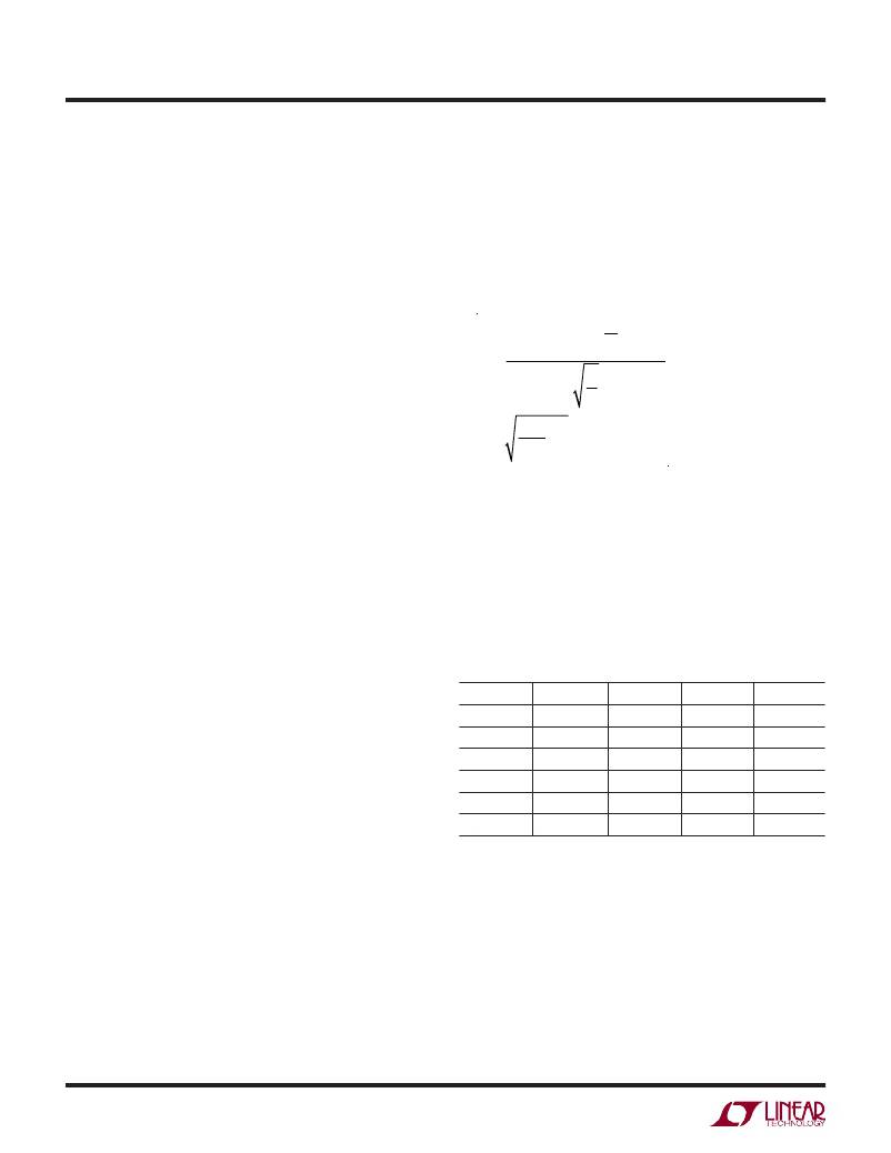
�peak� inrush� current� can� be� estimated� as� follows:�
�resistance).� The� inductor� DCR� should� be� on� the� order� of�
�half� of� the� switch� on� resistance� for� its� channel:� 0.5Ω� for�
�Boost1,� 0.4Ω� for� the� inverter� and� 1Ω� for� Boost3.� For� robust�
�applications,� the� inductors� should� have� current� ratings�
�I� P� =�
�(V� VIN� ?� 0.6)� ?� e�
�L�
�?� 1�
�?�
�tan� ?� 1� (� ?� )�
�corresponding� to� their� respective� peak� current� during�
�C�
�regulation.� Furthermore,� with� no� soft-start,� the� inductor�
�should� also� be� able� to� withstand� temporary� high� start-up�
�currents� of� 1A,� 1.1A� and� 480mA� for� the� Boost1,� inverter�
�?=�
�4L�
�R� 2� C�
�?� 1�
�and� Boost3� channels� respectively� (typ,� refer� to� the� Typical�
�Performance� Characteristics� curves).�
�Capacitor� Selection�
�The� small� size� of� ceramic� capacitors� makes� them� suitable�
�for� LT3587� applications.� X5R� and� X7R� types� of� ceramic�
�capacitors� are� recommended� because� they� retain� their�
�capacitance� over� wider� voltage� and� temperature� ranges�
�than� other� types� such� as� Y5V� or� Z5U.� A� 1μF� input� ca-�
�pacitor� is� suf?cient� for� most� LT3587� applications.� The�
�where� L� is� the� inductance,� C� is� the� capacitance� and� R� is�
�the� total� series� resistance� in� the� inrush� current� path,� which�
�includes� the� resistance� of� the� inductor� and� the� Schottky�
�diode.� Note� that� in� this� equation,� we� model� the� Schottky�
�as� having� a� ?xed� 0.6V� drop.�
�Table� 1� gives� inrush� peak� currents� for� some� component�
�selections.� Note� that� inrush� current� is� not� a� concern� if� the�
�input� voltage� rises� slowly.�
�Table� 1.� Inrush� Peak� Current�
�output� capacitors� required� for� stability� depend� on� the�
�application.� For� most� applications,� the� output� capacitor�
�values� required� are:� 10μF� for� the� Boost1� channel,� 22μF�
�for� the� inverter� channel� and� 2.2μF� for� the� Boost3� chan-�
�nel.� The� inverter� requires� a� 2.2μF� ?ying� capacitor.� Note�
�that� this� ?ying� capacitor� needs� a� voltage� rating� of� at� least�
�V� IN� +� |V� NEG� |.�
�V� VIN� (V)�
�5�
�5�
�5�
�3.6�
�3.6�
�3.6�
�R� (� Ω� )�
�0.68�
�0.68�
�0.68�
�0.745�
�0.745�
�0.745�
�L� (μH)�
�15�
�22�
�10�
�15�
�22�
�10�
�C� (μF)�
�10�
�2.2�
�2.2�
�10�
�2.2�
�2.2�
�I� P� (A)�
�2.48�
�1.19�
�1.64�
�1.64�
�0.80�
�1.10�
�Inrush� Current�
�When� a� supply� voltage� is� abruptly� applied� to� the� V� IN� pin,�
�the� voltage� difference� between� the� V� IN� pin� and� the� CAP�
�pins� generates� inrush� current.� For� the� case� of� the� Boost1�
�channel,� the� inrush� current� ?ows� from� the� input� through�
�the� inductor� L1� and� the� Schottky� D� S1� to� charge� the� Boost1�
�output� capacitor� C1.� Similarly� for� the� Boost3� channel,� the�
�inrush� current� ?ows� from� the� input� through� the� inductor�
�L4� and� the� Schottky� D� S3� to� charge� the� output� capacitor� C4.�
�Schottky� Diode� Selection�
�For� any� of� the� external� diode� (D� S1� ,� D� S2� and� D� S3� )� selec-�
�tions,� besides� having� suf?ciently� high� reverse� breakdown�
�voltage� to� withstand� the� output� voltage,� both� forward� volt-�
�age� drop� and� diode� capacitance� need� to� be� considered.�
�Schottky� diodes� rated� for� higher� current� usually� have� lower�
�forward� voltage� drops� and� larger� capacitance.� Although�
�lower� forward� voltage� drop� is� good� for� ef?ciency,� a� large�
�3587fc�
�10�
�相关PDF资料 |
PDF描述 |
|---|---|
| LT3640IFE#TRPBF | IC REG BUCK FIX/ADJ DL 28TSSOP |
| LT3641HFE#TRPBF | IC REG BUCK SYNC ADJ DL 28TSSOP |
| LT3650IMSE-8.4#TRPBF | IC CHARGER LI-ION 8.4V 2A 12MSOP |
| LT3652EMSE#PBF | IC BATTERY CHARGER SOLAR 12MSOP |
| LT3653IDCB#TRPBF | IC REG BUCK ADJ 1.2A 8DFN |
相关代理商/技术参数 |
参数描述 |
|---|---|
| LT3590 | 制造商:LINER 制造商全称:Linear Technology 功能描述:60V Triple Step-Down LED Driver Programmable Temperature Protection |
| LT3590EDC#PBF | 制造商:Linear Technology 功能描述:IC LED DRIVER BULK MODE 48V 制造商:Linear Technology 功能描述:IC, LED DRIVER, BULK MODE, 48V |
| LT3590EDC#TRMPBF | 功能描述:IC LED DRIVER WHITE BCKLGT 6-DFN RoHS:是 类别:集成电路 (IC) >> PMIC - LED 驱动器 系列:- 标准包装:6,000 系列:- 恒定电流:- 恒定电压:- 拓扑:开路漏极,PWM 输出数:4 内部驱动器:是 类型 - 主要:LED 闪烁器 类型 - 次要:- 频率:400kHz 电源电压:2.3 V ~ 5.5 V 输出电压:- 安装类型:表面贴装 封装/外壳:8-VFDFN 裸露焊盘 供应商设备封装:8-HVSON 包装:带卷 (TR) 工作温度:-40°C ~ 85°C 其它名称:935286881118PCA9553TK/02-TPCA9553TK/02-T-ND |
| LT3590EDC#TRPBF | 功能描述:IC LED DRIVER WHITE BCKLGT 6-DFN RoHS:是 类别:集成电路 (IC) >> PMIC - LED 驱动器 系列:- 标准包装:6,000 系列:- 恒定电流:- 恒定电压:- 拓扑:开路漏极,PWM 输出数:4 内部驱动器:是 类型 - 主要:LED 闪烁器 类型 - 次要:- 频率:400kHz 电源电压:2.3 V ~ 5.5 V 输出电压:- 安装类型:表面贴装 封装/外壳:8-VFDFN 裸露焊盘 供应商设备封装:8-HVSON 包装:带卷 (TR) 工作温度:-40°C ~ 85°C 其它名称:935286881118PCA9553TK/02-TPCA9553TK/02-T-ND |
| LT3590EDC-PBF | 制造商:LINER 制造商全称:Linear Technology 功能描述:48V Buck Mode LED Driver in SC70 and 2mm x 2mm DFN |
发布紧急采购,3分钟左右您将得到回复。