参数资料
| 型号: | LT8415IDDB#TRPBF |
| 厂商: | Linear Technology |
| 文件页数: | 8/12页 |
| 文件大小: | 0K |
| 描述: | IC REG BOOST ADJ 25MA 12DFN |
| 标准包装: | 2,500 |
| 类型: | 升压(升压) |
| 输出类型: | 可调式 |
| 输出数: | 1 |
| 输出电压: | 2.5 V ~ 40 V |
| 输入电压: | 2.5 V ~ 16 V |
| PWM 型: | 电流模式 |
| 频率 - 开关: | 800kHz |
| 电流 - 输出: | 25mA |
| 同步整流器: | 无 |
| 工作温度: | -40°C ~ 125°C |
| 安装类型: | 表面贴装 |
| 封装/外壳: | 12-WFDFN 裸露焊盘 |
| 包装: | 带卷 (TR) |
| 供应商设备封装: | 12-DFN-EP(3x2) |
�� �
�
�LT8415�
�APPLICATIONS� INFORMATION�
�Inductor� Selection�
�Several� inductors� that� work� well� with� the� LT8415� are� listed�
�in� Table� 1.� The� tables� are� not� complete,� and� there� are� many�
�other� manufacturers� and� devices� that� can� be� used.� Consult�
�each� manufacturer� for� more� detailed� information� and� for�
�their� entire� selection� of� related� parts,� as� many� different�
�sizes� and� shapes� are� available.�
�Inductors� with� a� value� of� 47μH� or� higher� are� recommended�
�for� most� LT8415� designs.� Inductors� with� low� core� losses�
�and� small� DCR� (copper� wire� resistance)� are� good� choices�
�for� LT8415� applications.� For� full� output� power,� the� induc-�
�tor� should� have� a� saturation� current� rating� higher� than�
�the� peak� inductor� current.� The� peak� inductor� current� can�
�be� calculated� as:�
�capacitor� placed� on� the� CAP� node� is� recommended� to� ?lter�
�the� inductor� current� while� a� 0.1μF� to� 1μF� capacitor� placed�
�on� the� V� OUT� node� will� give� excellent� transient� response�
�and� stability.� To� make� the� V� REF� pin� less� sensitive� to� noise,�
�putting� a� capacitor� on� the� V� REF� pin� is� recommended,� but�
�not� required.� A� 47nF� to� 220nF� 0402� capacitor� will� be� suf-�
�?cient.� See� also� Soft-Start� section� for� more� information�
�about� a� capacitor� across� V� REF� .� Table� 2� shows� a� list� of� several�
�capacitor� manufacturers.� Consult� the� manufacturers� for�
�more� detailed� information� and� for� their� entire� selection�
�of� related� parts.�
�Table� 2.� Recommended� Ceramic� Capacitor� Manufacturers�
�MANUFACTURER� PHONE� WEBSITE�
�Taiyo� Yuden� (408)� 573-4150� www.t-yuden.com�
�Murata� (814)� 237-1431� www.murata.com�
�I� PK� =� I� LIMIT�
�+�
�V� IN� ?� 150� ?� 10� ?� 6�
�L�
�mA�
�AVX�
�Kemet�
�TDK�
�(843)� 448-9411�
�(408)986-0424�
�(847)� 803-6100�
�www.avxcorp.com�
�www.kemet.com�
�www.tdk.com�
�where� the� worst� case� I� LIMIT� is� 30mA.� L� is� the� inductance�
�value� in� Henrys� and� V� IN� is� the� input� voltage� to� the� boost�
�circuit.�
�Table� 1.� Recommended� Inductors� for� LT8415�
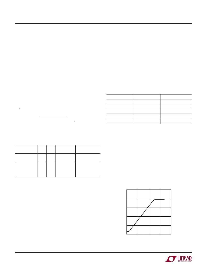
�Setting� Output� Voltage�
�The� output� voltage� is� set� by� the� FBP� pin� voltage,� and� V� OUT�
�is� equal� to� 31.85� ?� V� FBP� when� the� output� is� regulated,�
�PART�
�LQH2MCN680K02�
�LQH32CN101K53�
�DO2010-683ML�
�DO2010-104ML�
�LPS3015-104ML�
�LPS3015-154ML�
�L�
�(μH)�
�68�
�100�
�68�
�100�
�100�
�150�
�DCR�
�(μH)�
�6.6�
�3.5�
�8.8�
�15.7�
�3.4�
�6.1�
�SIZE�
�(mm)�
�2.0� � 1.6� � 0.9�
�3.2� � 2.5� � 2.0�
�2.0� � 2.0� � 1.0�
�2.0� � 2.0� � 1.0�
�3.0� � 3.0� � 1.4�
�3.0� � 3.0� � 1.4�
�VENDOR�
�Murata�
�www.murata.com�
�Coilcraft�
�www.coilcraft.com�
�shown� in� Figure� 1.� Since� the� V� REF� pin� provides� a� good�
�reference� (~1.235V),� the� FBP� voltage� can� be� easily� set� by�
�a� resistor� divider� from� the� V� REF� pin� to� ground.� The� series�
�resistance� of� this� resistor� divider� should� be� kept� larger� than�
�200K� to� prevent� loading� down� the� V� REF� pin.� The� FBP� pin�
�can� also� be� biased� directly� by� an� external� reference.� For�
�over� voltage� protection,� the� output� voltage� is� limited� to�
�40V.� Therefore,� if� V� FBP� is� higher� than� 1.235V,� the� output�
�Capacitor� Selection�
�voltage� will� stay� at� 40V.�
�50�
�The� small� size� and� low� ESR� of� ceramic� capacitors� make�
�them� suitable� for� most� LT8415� applications.� X5R� and�
�X7R� types� are� recommended� because� they� retain� their�
�capacitance� over� wider� voltage� and� temperature� ranges�
�than� other� types� such� as� Y5V� or� Z5U.� A� 2.2μF� or� higher�
�input� capacitor� and� a� 0.1μF� to� 1μF� output� capacitor� are�
�suf?cient� for� most� applications.� Always� use� a� capacitor�
�with� a� suf?cient� voltage� rating.� Many� ceramic� capacitors�
�rated� at� 0.1μF� to� 1μF� have� greatly� reduced� capacitance�
�40�
�30�
�20�
�10�
�when� bias� voltages� are� applied.� Be� sure� to� check� actual�
�0�
�0�
�0.5�
�1� 1.5�
�2�
�capacitance� at� the� desired� output� voltage.� Generally� a� 0603�
�FBP� VOLTAGE� (V)�
�8415� F01�
�or� 0805� size� capacitor� will� be� adequate.� A� 0.1μF� to� 1μF�
�Figure� 1.� FBP� to� V� OUT� Transfer� Curve�
�8415f�
�8�
�相关PDF资料 |
PDF描述 |
|---|---|
| LT8582IDKD#TRPBF | IC REG MULTI CONFIG ADJ 3A 24DFN |
| LTC1043CSW#TRPBF | IC BUILDNG BLK SW-CAP DUAL18SOIC |
| LTC1044CS8#TRPBF | IC REG MULTI CONFIG 20MA 8SOIC |
| LTC1046IS8#TRPBF | IC REG SWITCHD CAP DIV INV 8SOIC |
| LTC1142LCG-ADJ#TRPBF | IC REG CTRLR BUCK PWM CM 28-SSOP |
相关代理商/技术参数 |
参数描述 |
|---|---|
| LT8500EUHH#PBF | 功能描述:IC PWM GENERATOR 56-QFN RoHS:是 类别:集成电路 (IC) >> 时钟/计时 - 专用 系列:- 标准包装:1 系列:- 类型:时钟/频率发生器,多路复用器 PLL:是 主要目的:存储器,RDRAM 输入:晶体 输出:LVCMOS 电路数:1 比率 - 输入:输出:1:2 差分 - 输入:输出:无/是 频率 - 最大:400MHz 电源电压:3 V ~ 3.6 V 工作温度:0°C ~ 85°C 安装类型:表面贴装 封装/外壳:16-TSSOP(0.173",4.40mm 宽) 供应商设备封装:16-TSSOP 包装:Digi-Reel® 其它名称:296-6719-6 |
| LT8500EUHH#TRPBF | 功能描述:IC PWM GENERATOR 56-QFN RoHS:是 类别:集成电路 (IC) >> 时钟/计时 - 专用 系列:- 标准包装:28 系列:- 类型:时钟/频率发生器 PLL:是 主要目的:Intel CPU 服务器 输入:时钟 输出:LVCMOS 电路数:1 比率 - 输入:输出:3:22 差分 - 输入:输出:无/是 频率 - 最大:400MHz 电源电压:3.135 V ~ 3.465 V 工作温度:0°C ~ 85°C 安装类型:表面贴装 封装/外壳:64-TFSOP (0.240",6.10mm 宽) 供应商设备封装:64-TSSOP 包装:管件 |
| LT8500IUHH#PBF | 功能描述:IC PWM GENERATOR 56-QFN RoHS:是 类别:集成电路 (IC) >> 时钟/计时 - 专用 系列:- 标准包装:28 系列:- 类型:时钟/频率发生器 PLL:是 主要目的:Intel CPU 服务器 输入:时钟 输出:LVCMOS 电路数:1 比率 - 输入:输出:3:22 差分 - 输入:输出:无/是 频率 - 最大:400MHz 电源电压:3.135 V ~ 3.465 V 工作温度:0°C ~ 85°C 安装类型:表面贴装 封装/外壳:64-TFSOP (0.240",6.10mm 宽) 供应商设备封装:64-TSSOP 包装:管件 |
| LT8500IUHH#TRPBF | 功能描述:IC PWM GENERATOR 56-QFN RoHS:是 类别:集成电路 (IC) >> 时钟/计时 - 专用 系列:- 标准包装:28 系列:- 类型:时钟/频率发生器 PLL:是 主要目的:Intel CPU 服务器 输入:时钟 输出:LVCMOS 电路数:1 比率 - 输入:输出:3:22 差分 - 输入:输出:无/是 频率 - 最大:400MHz 电源电压:3.135 V ~ 3.465 V 工作温度:0°C ~ 85°C 安装类型:表面贴装 封装/外壳:64-TFSOP (0.240",6.10mm 宽) 供应商设备封装:64-TSSOP 包装:管件 |
| LT-8501M | 制造商:Mencom 功能描述: |
发布紧急采购,3分钟左右您将得到回复。