- 您现在的位置:买卖IC网 > PDF目录1827 > LTC1703IG#TRPBF (Linear Technology)IC REG SW DUAL SYNC VID 28SSOP PDF资料下载
参数资料
| 型号: | LTC1703IG#TRPBF |
| 厂商: | Linear Technology |
| 文件页数: | 31/36页 |
| 文件大小: | 0K |
| 描述: | IC REG SW DUAL SYNC VID 28SSOP |
| 标准包装: | 2,000 |
| 应用: | 控制器,移动式 Intel Pentium? III |
| 输入电压: | 3 V ~ 7 V |
| 输出数: | 2 |
| 输出电压: | 0.9 V ~ 2 V |
| 工作温度: | -40°C ~ 85°C |
| 安装类型: | 表面贴装 |
| 封装/外壳: | 28-SSOP(0.209",5.30mm 宽) |
| 供应商设备封装: | 28-SSOP |
| 包装: | 带卷 (TR) |
第1页第2页第3页第4页第5页第6页第7页第8页第9页第10页第11页第12页第13页第14页第15页第16页第17页第18页第19页第20页第21页第22页第23页第24页第25页第26页第27页第28页第29页第30页当前第31页第32页第33页第34页第35页第36页
�� �
�
�LTC1703�
�APPLICATIO� S� I� FOR� ATIO�
�specified� tolerance,� the� output� voltage� will� ride� high� when�
�I� LOAD� is� low� and� will� ride� low� when� I� LOAD� is� high.� Compared�
�to� a� traditional� regulator,� a� voltage� positioning� regulator�
�can� theoretically� stand� as� much� as� twice� the� ESR� drop�
�across� the� output� capacitor� while� maintaining� output�
�voltage� regulation.� This� means� smaller,� cheaper� output�
�capacitors� can� be� used� while� keeping� the� output� voltage�
�within� acceptable� limits.�
�load� which� can� dissipate� 2.5W� continuously� or� 50W� if�
�pulsed� with� a� 5%� duty� cycle,� enough� for� most� LTC1703�
�circuits.� Solder� the� MOSFET� and� the� resistor(s)� as� close� to�
�the� output� of� the� LTC1703� circuit� as� possible� and� set� up�
�the� signal� generator� to� pulse� at� a� 100Hz� rate� with� a� 5%� duty�
�cycle.� This� pulses� the� LTC1703� with� 500� μ� s� transients�
�10ms� apart,� adequate� for� viewing� the� entire� transient�
�recovery� time� for� both� positive� and� negative� transitions�
�while� keeping� the� load� resistor� cool.�
�Measurement� Techniques�
�Measuring� transient� response� presents� a� challenge� in� two�
�respects:� obtaining� an� accurate� measurement� and� gener-�
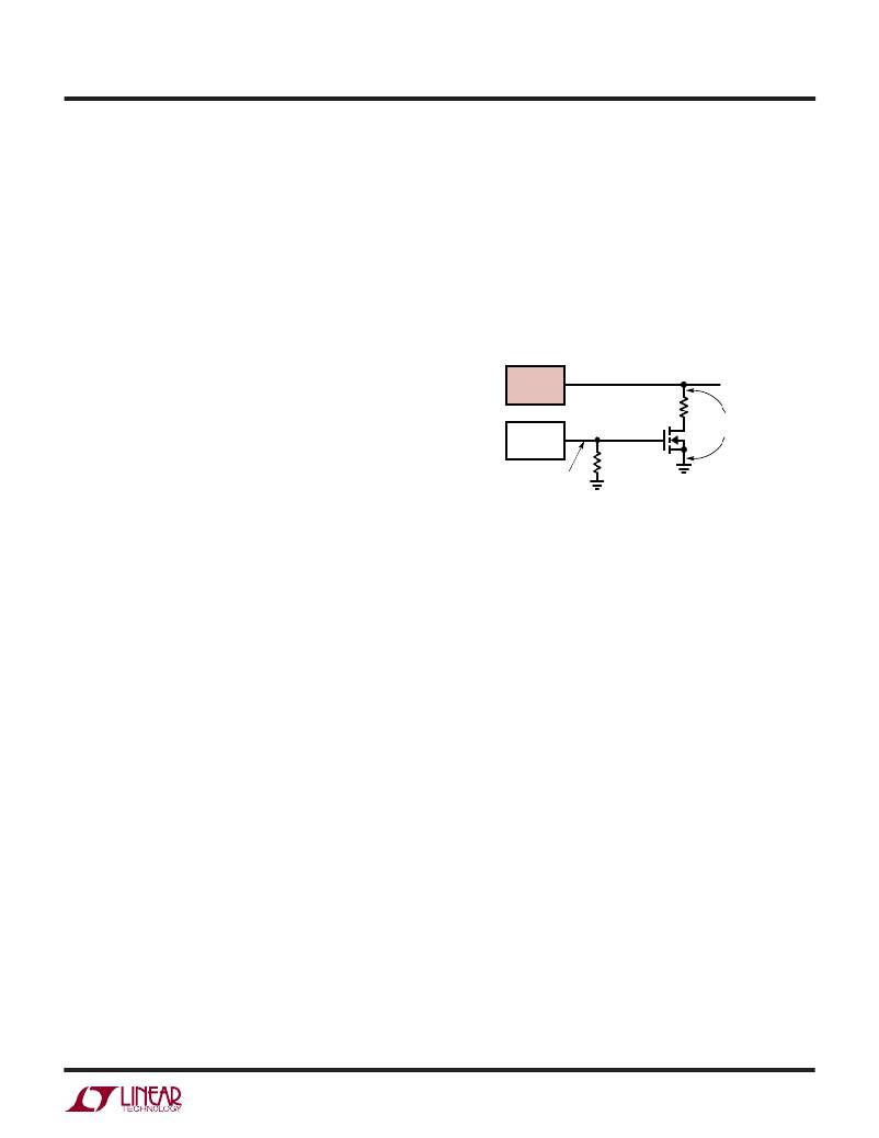
�LTC1703�
�V� OUT�
�ating� a� suitable� transient� to� use� to� test� the� circuit.� Output�
�measurements� should� be� taken� with� a� scope� probe�
�directly� across� the� output� capacitor.� Proper� high� fre-�
�quency� probing� techniques� should� be� used.� In� particular,�
�don’t� use� the� 6"� ground� lead� that� comes� with� the� probe!�
�Use� an� adapter� that� fits� on� the� tip� of� the� probe� and� has� a�
�PULSE�
�GENERATOR�
�0V� TO� 10V�
�100Hz,� 5%�
�DUTY� CYCLE�
�R� LOAD�
�IRFZ44� OR�
�EQUIVALENT�
�50� ?�
�LOCATE� CLOSE�
�TO� THE� OUTPUT�
�1703� F18�
�short� ground� clip� to� ensure� that� inductance� in� the� ground�
�path� doesn’t� cause� a� bigger� spike� than� the� transient� signal�
�being� measured.� Conveniently,� the� typical� probe� tip� ground�
�clip� is� spaced� just� right� to� span� the� leads� of� a� typical� output�
�capacitor.� Make� sure� the� bandwidth� limit� on� the� scope� is�
�turned� off,� since� a� significant� portion� of� the� transient�
�energy� occurs� above� the� 20MHz� cutoff.�
�Now� that� we� know� how� to� measure� the� signal,� we� need� to�
�have� something� to� measure.� The� ideal� situation� is� to� use�
�the� actual� load� for� the� test,� and� switch� it� on� and� off� while�
�watching� the� output.� If� this� isn’t� convenient,� a� current� step�
�generator� is� needed.� This� generator� needs� to� be� able� to�
�turn� on� and� off� in� nanoseconds� to� simulate� a� typical�
�switching� logic� load,� so� stray� inductance� and� long� clip�
�leads� between� the� LTC1703� and� the� transient� generator�
�must� be� minimized.�
�Figure� 18� shows� an� example� of� a� simple� transient� genera-�
�tor.� Be� sure� to� use� a� noninductive� resistor� as� the� load�
�element� —many� power� resistors� use� an� inductive� spiral�
�pattern� and� are� not� suitable� for� use� here.� A� simple� solution�
�is� to� take� ten� 1/4W� film� resistors� and� wire� them� in� parallel�
�Figure� 18.� Transient� Load� Generator�
�Changing� the� Output� Voltage� on� the� Fly�
�The� voltage� at� side� 1� of� the� LTC1703� can� be� changed� on� the�
�fly� by� changing� the� VID� code� while� the� output� is� enabled,�
�but� care� must� be� taken� to� avoid� tripping� the� overvoltage�
�fault� circuit.� Stepping� the� voltage� upwards� abruptly� is� safe,�
�but� stepping� down� quickly� by� more� than� 15%� can� leave� the�
�system� in� a� state� where� the� output� voltage� is� still� at� the� old�
�higher� level,� but� the� feedback� node� is� set� to� expect� a� new,�
�substantially� lower� voltage.� If� this� condition� persists� for�
�more� than� 10� μ� s,� the� overvoltage� fault� circuitry� will� fire� and�
�latch� off� the� LTC1703.�
�The� simplest� solution� is� to� disable� the� fault� circuit� by�
�grounding� the� FAULT� pin.� Systems� that� must� keep� the�
�fault� circuit� active� should� ensure� that� the� output� voltage� is�
�never� programmed� to� step� down� by� more� than� 15%� in� any�
�single� step.� The� safest� strategy� is� to� step� the� output� down�
�by� 10%� or� less� at� a� time� and� wait� for� the� output� to� settle�
�to� the� new� value� before� taking� subsequent� steps.�
�to� get� the� desired� value.� This� gives� a� noninductive� resistive�
�1703fa�
�31�
�相关PDF资料 |
PDF描述 |
|---|---|
| LTC1707IS8#TRPBF | IC REG BUCK SYNC ADJ 0.6A 8SOIC |
| LTC1708EG-PG#TRPBF | IC REG CTRLR BUCK PWM CM 36-SSOP |
| LTC1709EG-7#TRPBF | IC REG CTRLR BUCK PWM CM 36-SSOP |
| LTC1709EG-8#TRPBF | IC REG CTRLR BUCK PWM CM 36-SSOP |
| LTC1709EG#PBF | IC REG CTRLR BUCK PWM CM 36-SSOP |
相关代理商/技术参数 |
参数描述 |
|---|---|
| LTC1704BEGN | 功能描述:IC REG DL BUCK/LINEAR 16-SSOP RoHS:否 类别:集成电路 (IC) >> PMIC - 稳压器 - 线性 + 切换式 系列:- 标准包装:2,500 系列:- 拓扑:降压(降压)同步(3),线性(LDO)(2) 功能:任何功能 输出数:5 频率 - 开关:300kHz 电压/电流 - 输出 1:控制器 电压/电流 - 输出 2:控制器 电压/电流 - 输出 3:控制器 带 LED 驱动器:无 带监控器:无 带序列发生器:是 电源电压:5.6 V ~ 24 V 工作温度:-40°C ~ 85°C 安装类型:* 封装/外壳:* 供应商设备封装:* 包装:* |
| LTC1704BEGN#PBF | 功能描述:IC REG DL BUCK/LINEAR 16-SSOP RoHS:是 类别:集成电路 (IC) >> PMIC - 稳压器 - 线性 + 切换式 系列:- 标准包装:2,500 系列:- 拓扑:降压(降压)同步(3),线性(LDO)(2) 功能:任何功能 输出数:5 频率 - 开关:300kHz 电压/电流 - 输出 1:控制器 电压/电流 - 输出 2:控制器 电压/电流 - 输出 3:控制器 带 LED 驱动器:无 带监控器:无 带序列发生器:是 电源电压:5.6 V ~ 24 V 工作温度:-40°C ~ 85°C 安装类型:* 封装/外壳:* 供应商设备封装:* 包装:* |
| LTC1704BEGN#TR | 功能描述:IC REG DL BUCK/LINEAR 16-SSOP RoHS:否 类别:集成电路 (IC) >> PMIC - 稳压器 - 线性 + 切换式 系列:- 标准包装:2,500 系列:- 拓扑:降压(降压)同步(3),线性(LDO)(2) 功能:任何功能 输出数:5 频率 - 开关:300kHz 电压/电流 - 输出 1:控制器 电压/电流 - 输出 2:控制器 电压/电流 - 输出 3:控制器 带 LED 驱动器:无 带监控器:无 带序列发生器:是 电源电压:5.6 V ~ 24 V 工作温度:-40°C ~ 85°C 安装类型:* 封装/外壳:* 供应商设备封装:* 包装:* |
| LTC1704BEGN#TRPBF | 功能描述:IC REG DL BUCK/LINEAR 16-SSOP RoHS:是 类别:集成电路 (IC) >> PMIC - 稳压器 - 线性 + 切换式 系列:- 标准包装:2,500 系列:- 拓扑:降压(降压)同步(3),线性(LDO)(2) 功能:任何功能 输出数:5 频率 - 开关:300kHz 电压/电流 - 输出 1:控制器 电压/电流 - 输出 2:控制器 电压/电流 - 输出 3:控制器 带 LED 驱动器:无 带监控器:无 带序列发生器:是 电源电压:5.6 V ~ 24 V 工作温度:-40°C ~ 85°C 安装类型:* 封装/外壳:* 供应商设备封装:* 包装:* |
| LTC1704EGN | 功能描述:IC REG DL BUCK/LINEAR 16SSOP RoHS:否 类别:集成电路 (IC) >> PMIC - 稳压器 - 线性 + 切换式 系列:- 标准包装:2,500 系列:- 拓扑:降压(降压)同步(3),线性(LDO)(2) 功能:任何功能 输出数:5 频率 - 开关:300kHz 电压/电流 - 输出 1:控制器 电压/电流 - 输出 2:控制器 电压/电流 - 输出 3:控制器 带 LED 驱动器:无 带监控器:无 带序列发生器:是 电源电压:5.6 V ~ 24 V 工作温度:-40°C ~ 85°C 安装类型:* 封装/外壳:* 供应商设备封装:* 包装:* |
发布紧急采购,3分钟左右您将得到回复。