- 您现在的位置:买卖IC网 > PDF目录14007 > LTC3548IMSE#PBF (Linear Technology)IC REG BUCK SYNC ADJ DL 10MSOP PDF资料下载
参数资料
| 型号: | LTC3548IMSE#PBF |
| 厂商: | Linear Technology |
| 文件页数: | 9/16页 |
| 文件大小: | 0K |
| 描述: | IC REG BUCK SYNC ADJ DL 10MSOP |
| 标准包装: | 50 |
| 类型: | 降压(降压) |
| 输出类型: | 可调式 |
| 输出数: | 2 |
| 输出电压: | 0.6 V ~ 5 V |
| 输入电压: | 2.5 V ~ 5.5 V |
| PWM 型: | 电流模式,混合 |
| 频率 - 开关: | 2.25MHz |
| 电流 - 输出: | 400mA,800mA |
| 同步整流器: | 是 |
| 工作温度: | -40°C ~ 85°C |
| 安装类型: | 表面贴装 |
| 封装/外壳: | 10-TFSOP,10-MSOP(0.118",3.00mm 宽)裸露焊盘 |
| 包装: | 管件 |
| 供应商设备封装: | 10-MSOP 裸露焊盘 |
�� �
�
�LTC3548�
�APPLICATIONS� INFORMATION�
�tantalum� capacitors� are� all� available� in� surface� mount�
�packages.� The� OS-CON� semiconductor� dielectric� capacitor�
�available� from� Sanyo� has� the� lowest� ESR� (size)� product�
�of� any� aluminum� electrolytic� at� a� somewhat� higher� price.�
�Special� polymer� capacitors,� such� as� Sanyo� POSCAP,�
�Panasonic� Special� Polymer� (SP),� and� Kemet� A700,� of-�
�fer� very� low� ESR,� but� have� a� lower� capacitance� density�
�than� other� types.� Tantalum� capacitors� have� the� highest�
�capacitance� density,� but� they� have� a� larger� ESR� and� it�
�is� critical� that� the� capacitors� are� surge� tested� for� use� in�
�switching� power� supplies.� An� excellent� choice� is� the� AVX�
�TPS� series� of� surface� mount� tantalums,� available� in� case�
�heights� ranging� from� 2mm� to� 4mm.� Aluminum� electrolytic�
�capacitors� have� a� signi?cantly� larger� ESR,� and� are� often�
�used� in� extremely� cost-sensitive� applications� provided� that�
�consideration� is� given� to� ripple� current� ratings� and� long�
�term� reliability.� Ceramic� capacitors� have� the� lowest� ESR�
�and� cost,� but� also� have� the� lowest� capacitance� density,�
�a� high� voltage� and� temperature� coef?cient,� and� exhibit�
�audible� piezoelectric� effects.� In� addition,� the� high� Q� of�
�ceramic� capacitors� along� with� trace� inductance� can� lead�
�to� signi?cant� ringing.�
�ESL� before� ESR� becomes� effective.� Also,� ceramic� caps� are�
�prone� to� temperature� effects� which� requires� the� designer�
�to� check� loop� stability� over� the� operating� temperature�
�range.� To� minimize� their� large� temperature� and� voltage�
�coef?cients,� only� X5R� or� X7R� ceramic� capacitors� should�
�be� used.� A� good� selection� of� ceramic� capacitors� is� available�
�from� Taiyo� Yuden,� AVX,� Kemet,� TDK� and� Murata.�
�Great� care� must� be� taken� when� using� only� ceramic� input�
�and� output� capacitors.� When� a� ceramic� capacitor� is� used�
�at� the� input� and� the� power� is� being� supplied� through� long�
�wires,� such� as� from� a� wall� adapter,� a� load� step� at� the� output�
�can� induce� ringing� at� the� V� IN� pin.� At� best,� this� ringing� can�
�couple� to� the� output� and� be� mistaken� as� loop� instability.�
�At� worst,� the� ringing� at� the� input� can� be� large� enough� to�
�damage� the� part.�
�Since� the� ESR� of� a� ceramic� capacitor� is� so� low,� the� input�
�and� output� capacitor� must� instead� ful?ll� a� charge� storage�
�requirement.� During� a� load� step,� the� output� capacitor� must�
�instantaneously� supply� the� current� to� support� the� load�
�until� the� feedback� loop� raises� the� switch� current� enough�
�to� support� the� load.� The� time� required� for� the� feedback�
�SW2�
�V� IN� =� 2.5V�
�TO� 5.5V�
�V� OUT2�
�C� IN�
�L2�
�C5�
�BM*�
�PS*�
�RUN2� V� IN�
�MODE/SYNC�
�LTC3548�
�RUN1�
�POR�
�SW1�
�R5�
�POWER-ON�
�RESET�
�L1�
�C4�
�V� OUT1�
�loop� to� respond� is� dependent� on� the� compensation� and� the�
�output� capacitor� size.� Typically,� 3� to� 4� cycles� are� required� to�
�respond� to� a� load� step,� but� only� in� the� ?rst� cycle� does� the�
�output� drop� linearly.� The� output� droop,� VDROOP� ,� is� usually�
�about� 2� to� 3� times� the� linear� drop� of� the� ?rst� cycle.� Thus,�
�C� OUT2�
�R4�
�R3�
�V� FB2� GND� V� FB1�
�*MODE/SYNC� =� 0V:� PULSE� SKIP�
�MODE/SYNC� =� V� IN� :� Burst� Mode�
�R1�
�R2�
�C� OUT1�
�3548� F02�
�a� good� place� to� start� is� with� the� output� capacitor� size� of�
�approximately:� More� capacitance� may� be� required� depend-�
�ing� on� the� duty� cycle� and� load� step� requirements.�
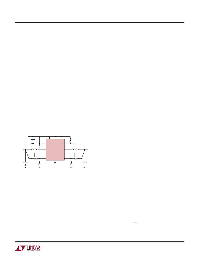
�Figure� 2.� LTC3548� General� Schematic�
�In� most� cases,� 0.1μF� to� 1μF� of� ceramic� capacitors� should�
�also� be� placed� close� to� the� LTC3548� in� parallel� with� the�
�main� capacitors� for� high� frequency� decoupling.�
�Ceramic� Input� and� Output� Capacitors�
�Higher� value,� lower� cost� ceramic� capacitors� are� now� be-�
�coming� available� in� smaller� case� sizes.� These� are� tempting�
�for� switching� regulator� use� because� of� their� very� low� ESR.�
�In� most� applications,� the� input� capacitor� is� merely� required�
�to� supply� high� frequency� bypassing,� since� the� impedance�
�to� the� supply� is� very� low.� A� 10μF� ceramic� capacitor� is�
�usually� enough� for� these� conditions.�
�Setting� the� Output� Voltage�
�The� LTC3548� develops� a� 0.6V� reference� voltage� between�
�the� feedback� pin,� V� FB� ,� and� the� ground� as� shown� in�
�Figure� 2.� The� output� voltage� is� set� by� a� resistive� divider�
�according� to� the� following� formula:�
�V� OUT� =� 0.6V� ?� 1� +�
�Unfortunately, the ESR is so low that it can cause loop�
�stability� problems.� Solid� tantalum� capacitor� ESR� generates�
�a� loop� “zero”� at� 5kHz� to� 50kHz� that� is� instrumental� in� giving�
�?�
�?�
�R2� ?�
�R1� ?� ?�
�acceptable� loop� phase� margin.� Ceramic� capacitors� remain�
�capacitive� to� beyond� 300kHz� and� usually� resonate� with� their�
�Keeping� the� current� small� (<5μA)� in� these� resistors� maxi-�
�mizes� ef?ciency,� but� making� them� too� small� may� allow�
�3548fc�
�9�
�相关PDF资料 |
PDF描述 |
|---|---|
| EBM28DSAS | CONN EDGECARD 56POS R/A .156 SLD |
| LTC3548IDD#PBF | IC REG BUCK SYNC ADJ DL 10DFN |
| EEM44DRYF | CONN EDGECARD 88POS DIP .156 SLD |
| HM71S-0603332LFTR | SHIELDED POWER INDUCTORS |
| ESM25DRSS | CONN EDGECARD 50POS DIP .156 SLD |
相关代理商/技术参数 |
参数描述 |
|---|---|
| LTC3548IMSE-TRPBF | 制造商:LINER 制造商全称:Linear Technology 功能描述:Dual Synchronous, 400mA/800mA, 2.25MHz Step-Down DC/DC Regulator |
| LTC3549 | 制造商:LINER 制造商全称:Linear Technology 功能描述:250mA Low VIN Buck Regulator in 2mm × 3mm DFN |
| LTC3549EDCB | 制造商:LINER 制造商全称:Linear Technology 功能描述:250mA Low VIN Buck Regulator in 2mm × 3mm DFN |
| LTC3549EDCB#PBF | 制造商:Linear Technology 功能描述:VOLTAGE REGULATOR BUCK 2.25M 制造商:Linear Technology 功能描述:VOLTAGE REGULATOR, BUCK, 2.25MHZ, 250mA, DFN-6; Primary Input Voltage:5.5V; No. of Outputs:1; Output Current:250mA; No. of Pins:6; Operating Temperature Min:-40C; Operating Temperature Max:85C; Package / Case:6-DFN ;RoHS Compliant: Yes |
| LTC3549EDCB#TRM | 制造商:Linear Technology 功能描述:250MA, LOW VIN BUCK REGULATOR |
发布紧急采购,3分钟左右您将得到回复。