- 您现在的位置:买卖IC网 > PDF目录15273 > LTC3802EUH#TR (Linear Technology)IC REG CTRLR BUCK PWM VM 32-QFN PDF资料下载
参数资料
| 型号: | LTC3802EUH#TR |
| 厂商: | Linear Technology |
| 文件页数: | 23/28页 |
| 文件大小: | 0K |
| 描述: | IC REG CTRLR BUCK PWM VM 32-QFN |
| 标准包装: | 2,500 |
| 系列: | PolyPhase® |
| PWM 型: | 电压模式 |
| 输出数: | 2 |
| 频率 - 最大: | 850kHz |
| 占空比: | 92% |
| 电源电压: | 3 V ~ 30 V |
| 降压: | 是 |
| 升压: | 无 |
| 回扫: | 无 |
| 反相: | 无 |
| 倍增器: | 无 |
| 除法器: | 无 |
| Cuk: | 无 |
| 隔离: | 无 |
| 工作温度: | -40°C ~ 85°C |
| 封装/外壳: | 32-WFQFN 裸露焊盘 |
| 包装: | 带卷 (TR) |
第1页第2页第3页第4页第5页第6页第7页第8页第9页第10页第11页第12页第13页第14页第15页第16页第17页第18页第19页第20页第21页第22页当前第23页第24页第25页第26页第27页第28页
�� �
�
�LTC3802�
�APPLICATIO� S� I� FOR� ATIO�
�C� MILLER� =� Calulated� Miller� capacitance� using� the� gate�
�charge� curve� from� the� MOSFET� data� sheet�
�f� SW� =� Switching� frequency�
�Both� MOSFETs� have� conduction� losses� (I� 2� R)� while� the�
�topside� N-channel� equation� includes� an� additional� term�
�for� transition� losses,� which� peak� at� the� highest� input�
�voltage.� For� V� IN� <� 12V,� the� high� current� efficiency� gener-�
�ally� improves� with� larger� MOSFETs,� while� for� V� IN� >� 12V,�
�the� transition� losses� rapidly� increase� to� the� point� that� the�
�use� of� a� higher� R� DS(ON)� device� with� lower� C� MILLER� actually�
�provides� higher� efficiency.� The� bottom� MOSFET� losses�
�are� greatest� at� high� input� voltage� when� the� top� switch� duty�
�factor� is� low� or� during� a� short� circuit� when� the� bottom�
�switch� is� on� close� to� 100%� of� the� period.�
�Schottky� Diode� D1/D2� Selection�
�The� Schottky� diode� D1� shown� in� Figure� 7� conducts� during�
�the� dead� time� between� the� conduction� of� the� power�
�MOSFET� switches.� It� is� intended� to� prevent� the� body� diode�
�of� the� bottom� MOSFET� from� turning� on� and� storing� a�
�charge� during� the� dead� time,� which� can� cause� a� modest�
�(about� 1%)� efficiency� loss.� The� diode� can� be� rated� for�
�about� one� half� to� one� fifth� of� the� full� load� current� since� it�
�occurs� not� only� as� I� 2� R� dissipation� in� the� capacitor� itself,�
�but� also� in� overall� battery� efficiency.� For� mobile� applica-�
�tions,� the� input� capacitors� should� store� adequate� charge�
�to� keep� the� peak� battery� current� within� the� manufacturer’s�
�specifications.�
�The� input� capacitor� RMS� current� requirement� is� simplified�
�by� the� multiphase� architecture� and� its� impact� on� the�
�worst-case� RMS� current� drawn� through� the� input� network�
�(battery/fuse/capacitor).� It� can� be� shown� that� the� worst-�
�case� RMS� current� occurs� when� only� one� controller� is�
�operating.� The� controller� with� the� highest� (V� OUT� )(I� OUT� )�
�product� needs� to� be� used� to� determine� the� maximum� RMS�
�current� requirement.� Increasing� the� output� current� drawn�
�from� the� other� out-of-phase� controller� will� actually� de-�
�crease� the� input� RMS� ripple� current� from� this� maximum�
�value.� The� out-of-phase� technique� typically� reduces� the�
�input� capacitor’s� RMS� ripple� current� by� a� factor� of� 30%� to�
�70%� when� compared� to� a� single� phase� power� supply�
�solution.�
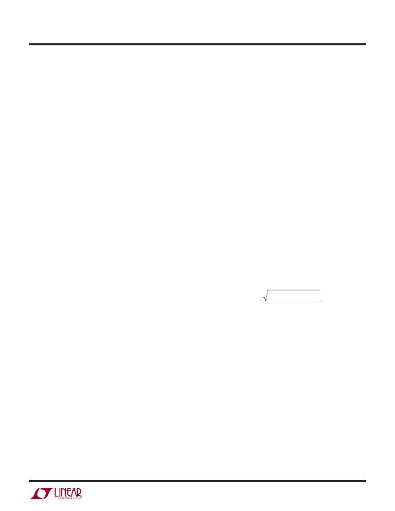
�In� continuous� mode,� the� source� current� of� the� top� N-channel�
�MOSFET� is� approximately� a� square� wave� of� duty� cycle�
�V� OUT� /V� IN� .� The� maximum� RMS� capacitor� current� is� given�
�by:�
�is� on� for� only� a� fraction� of� the� duty� cycle.� In� order� for� the�
�diode� to� be� effective,� the� inductance� between� it� and� the�
�bottom� MOSFET� must� be� as� small� as� possible,� mandating�
�I� RMS� ≈� I� OUT� (� MAX� )�
�V� OUT� (� V� IN� –� V� OUT� )�
�V� IN�
�that� these� components� be� placed� adjacently.�
�C� IN� Selection�
�The� input� bypass� capacitor� in� an� LTC3802� circuit� is�
�common� to� both� channels.� The� input� bypass� capacitor�
�gets� exercised� in� three� ways:� its� ESR� must� be� low� enough�
�to� keep� the� supply� drop� low� as� the� top� MOSFETs� turn� on,�
�its� RMS� current� capability� must� be� adequate� to� withstand�
�the� ripple� current� at� the� input,� and� the� capacitance� must� be�
�large� enough� to� maintain� the� input� voltage� until� the� input�
�supply� can� make� up� the� difference.� Generally,� a� capacitor�
�(particularly� a� non-ceramic� type)� that� meets� the� first� two�
�parameters� will� have� far� more� capacitance� than� is� required�
�to� keep� capacitance-based� droop� under� control.�
�The� input� capacitor’s� voltage� rating� should� be� at� least� 1.4�
�times� the� maximum� input� voltage.� Power� loss� due� to� ESR�
�This� formula� has� a� maximum� at� V� IN� =� 2V� OUT� ,� where�
�I� RMS� =� I� OUT� /2.� This� simple� worst-case� condition� is� com-�
�monly� used� for� design� because� even� significant� devia-�
�tions� do� not� offer� much� relief.� The� total� RMS� current� is�
�lower� when� both� controllers� are� operating� due� to� the�
�interleaving� of� current� pulses� through� the� input� capaci-�
�tors.� This� is� why� the� input� capacitance� requirement� calcu-�
�lated� above� for� the� worst-case� controller� is� adequate� for�
�the� dual� controller� design.�
�Note� that� capacitor� manufacturer’s� ripple� current� ratings�
�are� often� based� on� only� 2000� hours� of� life.� This� makes� it�
�advisable� to� further� derate� the� capacitor� or� to� choose� a�
�capacitor� rated� at� a� higher� temperature� than� required.�
�Several� capacitors� may� also� be� paralleled� to� meet� size� or�
�height� requirements� in� the� design.� Always� consult� the�
�manufacturer� if� there� is� any� question.�
�3802f�
�23�
�相关PDF资料 |
PDF描述 |
|---|---|
| VI-J5L-EW-F2 | CONVERTER MOD DC/DC 28V 100W |
| VI-J5L-EW-F1 | CONVERTER MOD DC/DC 28V 100W |
| H2BXG-10108-R4-ND | JUMPER-H1501TR/A2015R/X 8" |
| LTC3802EGN#TRPBF | IC REG CTRLR BUCK PWM VM 28-SSOP |
| H2BXG-10108-N4-ND | JUMPER-H1501TR/A2015N/X 8" |
相关代理商/技术参数 |
参数描述 |
|---|---|
| LTC3803ES6 | 制造商:Linear Technology 功能描述:DC DC Cntrlr Single-OUT Flyback Controller 9.2V to 75V Input 6-Pin TSOT-23 |
| LTC3803ES6#PBF | 制造商:Linear Technology 功能描述:DC DC Cntrlr Single-OUT Flyback Controller 6-Pin TSOT-23 Bulk 制造商:Linear Technology 功能描述:IC, DC-DC CONV; Primary Input Voltage:8V; No. of Outputs:1; Output Current:1A; No. of Pins:6; Operating Temperature Min:-40C; Operating Temperature Max:125C; MSL:MSL 1 - Unlimited; Leaded Process Compatible:Yes ;RoHS Compliant: Yes |
| LTC3803ES6#TR | 功能描述:IC REG CTRLR FLYBK PWM TSOT23-6 RoHS:否 类别:集成电路 (IC) >> PMIC - 稳压器 - DC DC 切换控制器 系列:- 标准包装:2,500 系列:- PWM 型:电流模式 输出数:1 频率 - 最大:500kHz 占空比:96% 电源电压:4 V ~ 36 V 降压:无 升压:是 回扫:无 反相:无 倍增器:无 除法器:无 Cuk:无 隔离:无 工作温度:-40°C ~ 125°C 封装/外壳:24-WQFN 裸露焊盘 包装:带卷 (TR) |
| LTC3803ES6#TRM | 功能描述:IC REG CTRLR FLYBK PWM TSOT23-6 RoHS:否 类别:集成电路 (IC) >> PMIC - 稳压器 - DC DC 切换控制器 系列:- 标准包装:2,500 系列:- PWM 型:电流模式 输出数:1 频率 - 最大:500kHz 占空比:96% 电源电压:4 V ~ 36 V 降压:无 升压:是 回扫:无 反相:无 倍增器:无 除法器:无 Cuk:无 隔离:无 工作温度:-40°C ~ 125°C 封装/外壳:24-WQFN 裸露焊盘 包装:带卷 (TR) |
| LTC3803ES6#TRMPBF | 功能描述:IC REG CTRLR FLYBK PWM TSOT23-6 RoHS:是 类别:集成电路 (IC) >> PMIC - 稳压器 - DC DC 切换控制器 系列:- 特色产品:LM3753/54 Scalable 2-Phase Synchronous Buck Controllers 标准包装:1 系列:PowerWise® PWM 型:电压模式 输出数:1 频率 - 最大:1MHz 占空比:81% 电源电压:4.5 V ~ 18 V 降压:是 升压:无 回扫:无 反相:无 倍增器:无 除法器:无 Cuk:无 隔离:无 工作温度:-5°C ~ 125°C 封装/外壳:32-WFQFN 裸露焊盘 包装:Digi-Reel® 产品目录页面:1303 (CN2011-ZH PDF) 其它名称:LM3754SQDKR |
发布紧急采购,3分钟左右您将得到回复。