- 您现在的位置:买卖IC网 > PDF目录69007 > LTC3823EUH (LINEAR TECHNOLOGY CORP) 4 A SWITCHING CONTROLLER, 200 kHz SWITCHING FREQ-MAX, PQCC32 PDF资料下载
参数资料
| 型号: | LTC3823EUH |
| 厂商: | LINEAR TECHNOLOGY CORP |
| 元件分类: | 稳压器 |
| 英文描述: | 4 A SWITCHING CONTROLLER, 200 kHz SWITCHING FREQ-MAX, PQCC32 |
| 封装: | 5 X 5 MM, PLASTIC, MO-220WHHD, QFN-32 |
| 文件页数: | 8/24页 |
| 文件大小: | 345K |
| 代理商: | LTC3823EUH |
LTC3823
3823fb
INTVCC Regulator
An internal P-channel low dropout regulator produces the
5V supply that powers the drivers and internal circuitry
withintheLTC3823.TheINTVCCpincansupplyupto50mA
RMS and must be bypassed to ground with a minimum
of 4.7F low ESR tantalum capacitor or other low ESR
capacitor. Good bypassing is necessary to supply the high
transient currents required by the MOSFET gate drivers.
ApplicationsusinglargeMOSFETswithahighinputvoltage
and high frequency of operation may cause the LTC3823
to exceed its maximum junction temperature rating or
RMS current rating. Most of the supply current drives the
MOSFETgates.Incontinuousmodeoperation,thiscurrent
isIGATEChG=f(Qg(TOP)+Qg(BOT)).Thejunctiontemperature
can be estimated from the equations given in Note 2 of the
Electrical Characteristics. For example, the LTC3823EGN
is limited to less than 23mA from a 30V supply:
TJ = 70°C + (23mA)(30V)(80°C/W) = 125°C
ForapplicationswheremorecurrentisneededthanINTVCC
can supply, INTVCC can be driver by an external supply
with a voltage higher than 5.35V. however, the INTVCC pin
should not exceed its absolute maximum voltage of 7V.
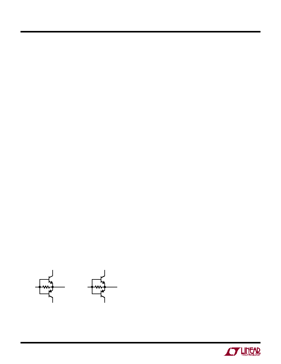
External Gate Drive Buffers
The LTC3823 drivers are adequate for driving up to about
50nC into MOSFET switches with RMS currents of 50mA.
Applications with larger MOSFET switches or operating
at frequencies requiring greater RMS currents will benefit
fromusingexternalgatedrivebufferssuchastheLTC1693.
Alternately, the external buffer circuit shown in Figure 6
can be used.
Soft-Start and Tracking
The LTC3823 has the ability to either soft start by itself with
a capacitor or track the output of another supply. When
the device is configured to soft start by itself, a capacitor
should be connected to the TRACK/SS pin. The LTC3823
is put in a low quiescent current shutdown state (30A) if
the RUN pin voltage is below 1.5V. The TRACK/SS pin is
actively pulled to ground in this shutdown state. Once the
RUN pin voltage is above 1.5V, the LTC3823 is powered
up. A soft-start current of 1.7A then starts to charge the
soft-startcapacitorCSS.PinZ1/SSENABLEmustbegrounded
for soft-start operation. Note that soft-start is achieved not
by limiting the maximum output current of the controller
but by controlling the ramp rate of the output voltage.
Current foldback is disabled during this soft-start phase.
During the soft-start phase, the LTC3823 is ramping the
reference voltage until it is 20% below the voltage set by
the VREFINpin.Theforcecontinuousmodeisalsodisabled
and PGOOD signal is forced low during this phase. The
total soft-start time can be calculated as:
tSOFTSTART = 0.5V CSS/1.7A
When the device is configured to track another supply,
the feedback voltage of the other supply is duplicated by
a resistor divider and applied to the TRACK/SS pin. Pin
Z1/SSENABLE should be tied to INTVCC to turn off the soft-
start current in this mode. Therefore, the voltage ramp rate
on this pin is determined by the ramp rate of the other
supply output voltage.
Output Voltage Tracking
The LTC3823 allows the user to program how its output
ramps up and down by means of the TRACK/SS pin.
Through this pin, the output can be set up to either co-
incidentally or ratiometrically track with another supply’s
output, as shown in Figure 7. In the following discussions,
VOUT1 refers to the master LTC3823’s output and VOUT2
refers to the slave LTC3823’s output.
To implement the coincident tracking in Figure 7a, connect
an additional resistive divider to VOUT1 and connect its
midpoint to the TRACK/SS pin of the slave IC. The ratio of
this divider should be selected the same as that of the slave
IC’s feedback divider shown in Figure 8. In this tracking
applications information
Q1
FMMT619
GATE
OF M1
TG
BOOST
SW
Q2
FMMT720
Q3
FMMT619
GATE
OF M2
BG
3823 F06
INTVCC
PGND
Q4
FMMT720
10
Ω
10
Ω
Figure 6. Optional External Gate Driver
相关PDF资料 |
PDF描述 |
|---|---|
| LTC3823EGN | 4 A SWITCHING CONTROLLER, 200 kHz SWITCHING FREQ-MAX, PDSO28 |
| LTC3823EUH#TR | 4 A SWITCHING CONTROLLER, 200 kHz SWITCHING FREQ-MAX, PQCC32 |
| LTC3823EGN#TR | 4 A SWITCHING CONTROLLER, 200 kHz SWITCHING FREQ-MAX, PDSO28 |
| LTC3827IUH | 3 A DUAL SWITCHING CONTROLLER, 580 kHz SWITCHING FREQ-MAX, PQCC32 |
| LTC3827IUH#TR | 3 A DUAL SWITCHING CONTROLLER, 580 kHz SWITCHING FREQ-MAX, PQCC32 |
相关代理商/技术参数 |
参数描述 |
|---|---|
| LTC3823EUH#PBF | 功能描述:IC REG CTRLR BUCK PWM CM 32-QFN RoHS:是 类别:集成电路 (IC) >> PMIC - 稳压器 - DC DC 切换控制器 系列:- 标准包装:2,000 系列:- PWM 型:电流模式 输出数:1 频率 - 最大:1MHz 占空比:50% 电源电压:9 V ~ 10 V 降压:无 升压:是 回扫:是 反相:无 倍增器:无 除法器:无 Cuk:无 隔离:无 工作温度:-40°C ~ 85°C 封装/外壳:8-TSSOP(0.173",4.40mm 宽) 包装:带卷 (TR) |
| LTC3823EUH#TRPBF | 功能描述:IC REG CTRLR BUCK PWM CM 32-QFN RoHS:是 类别:集成电路 (IC) >> PMIC - 稳压器 - DC DC 切换控制器 系列:- 标准包装:2,500 系列:- PWM 型:电流模式 输出数:1 频率 - 最大:500kHz 占空比:96% 电源电压:4 V ~ 36 V 降压:无 升压:是 回扫:无 反相:无 倍增器:无 除法器:无 Cuk:无 隔离:无 工作温度:-40°C ~ 125°C 封装/外壳:24-WQFN 裸露焊盘 包装:带卷 (TR) |
| LTC3823IGN#PBF | 功能描述:IC REG CTRLR BUCK PWM CM 28-SSOP RoHS:是 类别:集成电路 (IC) >> PMIC - 稳压器 - DC DC 切换控制器 系列:- 标准包装:2,000 系列:- PWM 型:电流模式 输出数:1 频率 - 最大:1MHz 占空比:50% 电源电压:9 V ~ 10 V 降压:无 升压:是 回扫:是 反相:无 倍增器:无 除法器:无 Cuk:无 隔离:无 工作温度:-40°C ~ 85°C 封装/外壳:8-TSSOP(0.173",4.40mm 宽) 包装:带卷 (TR) |
| LTC3823IGN#PBF | 制造商:Linear Technology 功能描述:IC SYNC STEP-DOWN DC/DC CTRL SSOP-28 |
| LTC3823IGN#TRPBF | 功能描述:IC REG CTRLR BUCK PWM CM 28-SSOP RoHS:是 类别:集成电路 (IC) >> PMIC - 稳压器 - DC DC 切换控制器 系列:- 标准包装:2,500 系列:- PWM 型:电流模式 输出数:1 频率 - 最大:500kHz 占空比:96% 电源电压:4 V ~ 36 V 降压:无 升压:是 回扫:无 反相:无 倍增器:无 除法器:无 Cuk:无 隔离:无 工作温度:-40°C ~ 125°C 封装/外壳:24-WQFN 裸露焊盘 包装:带卷 (TR) |
发布紧急采购,3分钟左右您将得到回复。