- 您现在的位置:买卖IC网 > PDF目录16300 > LTC4000EGN#PBF (Linear Technology)IC CHARGER BATTERY 28-SSOP PDF资料下载
参数资料
| 型号: | LTC4000EGN#PBF |
| 厂商: | Linear Technology |
| 文件页数: | 16/40页 |
| 文件大小: | 0K |
| 描述: | IC CHARGER BATTERY 28-SSOP |
| 产品培训模块: | LTC4000 60V Battery Charging Controller and Power Management |
| 标准包装: | 49 |
| 系列: | PowerPath™ |
| 功能: | 充电管理,电源管理 |
| 电池化学: | 多化学 |
| 电源电压: | 3 V ~ 60 V |
| 工作温度: | -40°C ~ 125°C |
| 安装类型: | 表面贴装 |
| 封装/外壳: | 28-SSOP(0.154",3.90mm 宽) |
| 供应商设备封装: | 28-SSOP |
| 包装: | 管件 |
第1页第2页第3页第4页第5页第6页第7页第8页第9页第10页第11页第12页第13页第14页第15页当前第16页第17页第18页第19页第20页第21页第22页第23页第24页第25页第26页第27页第28页第29页第30页第31页第32页第33页第34页第35页第36页第37页第38页第39页第40页
�� �
�
�LTC4000�
�APPLICATIONS� INFORMATION�
�R� IS� =�
�?� I� ILIM� =� IL� ?� 2.5μA�
�R� IL� =�
�I� ILIM(MAX)� (A)� =�
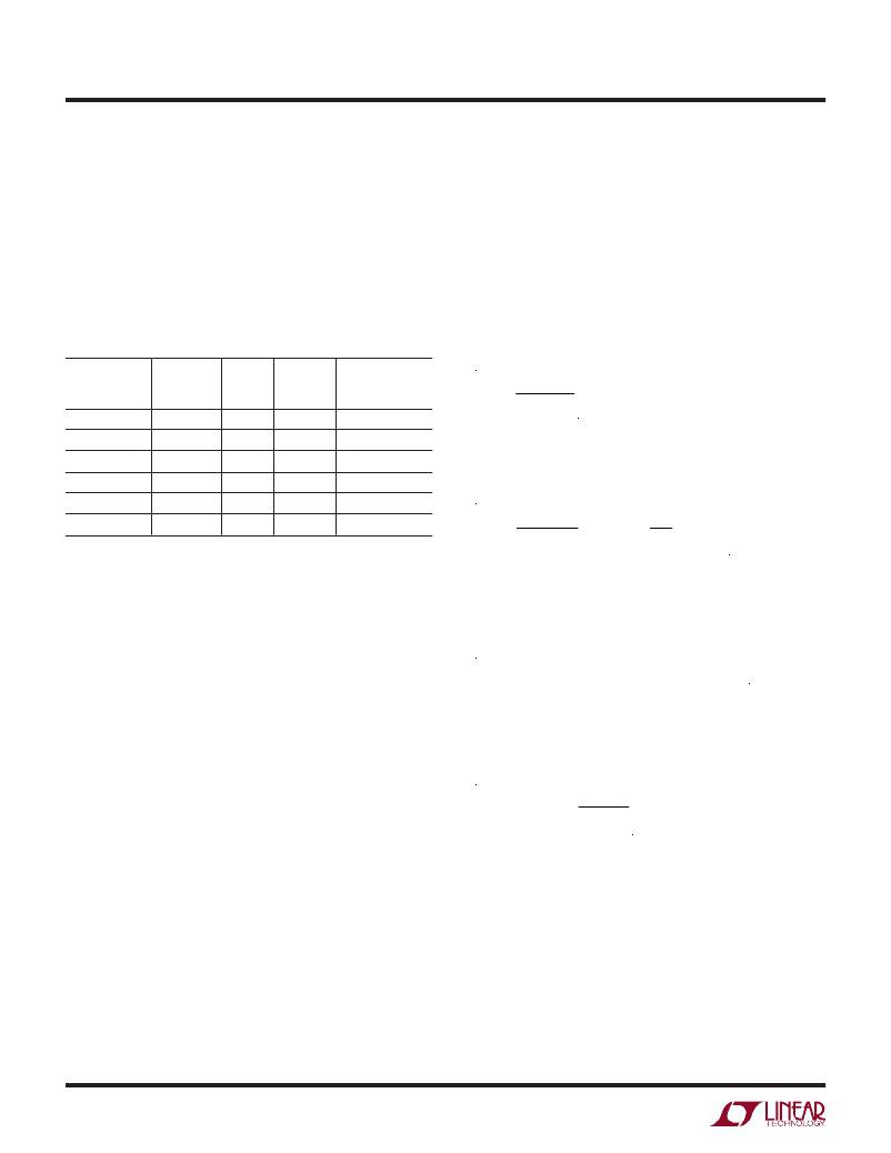
�InputIdealDiodePMOSSelection�
�The� input� external� PMOS� is� selected� based� on� the� expected�
�maximum� current,� power� dissipation� and� reverse� volt-�
�age� drop.� The� PMOS� must� be� able� to� withstand� a� gate� to�
�source� voltage� greater� than� V� IGATE(ON)� (15V� maximum)� or�
�the� maximum� regulated� voltage� at� the� IID� pin,� whichever�
�is� less.� A� few� appropriate� external� PMOS� for� a� number� of�
�different� requirements� are� shown� at� Table� 1.�
�Table 1. PMOS�
�R� DS(ON)� AT�
�V� GS� =� 10V� MAX� ID� MAX� VDS�
�PART� NUMBER� (Ω)� (A)� (V)� MANUFACTURER�
�SiA923EDJ� 0.054� 4.5� –20� Vishay�
�Si9407BDY� 0.120� 4.7� –60� Vishay�
�Si4401BDY� 0.014� 10.5� –40� Vishay�
�Si4435DDY� 0.024� 11.4� –30� Vishay�
�SUD19P06-60� 0.060� 18.3� –60� Vishay�
�Si7135DP� 0.004� 60� –30� Vishay�
�Note� that� in� general� the� larger� the� capacitance� seen� on�
�the� IGATE� pin,� the� slower� the� response� of� the� ideal� diode�
�driver.� The� fast� turn� off� and� turn� on� current� is� limited� to�
�–0.5mA� and� 0.7mA� typical� respectively� (I� IGATE(FASTOFF)� and�
�I� IGATE(FASTON)� ).� If� the� driver� can� not� react� fast� enough� to� a�
�sudden� increase� in� load� current,� most� of� the� extra� current�
�is� delivered� through� the� body� diode� of� the� external� PMOS.�
�This� increases� the� power� dissipation� momentarily.� It� is�
�important� to� ensure� that� the� PMOS� is� able� to� withstand�
�this� momentary� increase� in� power� dissipation.�
�The� operation� section� also� mentioned� that� an� external� 10M�
�pull-up� resistor� is� recommended� between� the� IGATE� pin�
�and� the� CSP� pin� when� the� IN� pin� voltage� is� expected� to�
�be� out� of� its� operating� range,� at� the� same� time� that� the�
�external� input� ideal� diode� PMOS� is� expected� to� be� com-�
�pletely� turned� off.� Note� that� this� additional� pull-up� resistor�
�increases� the� forward� voltage� regulation� of� the� ideal� diode�
�function� (V� IID,CSP� )� from� the� typical� value� of� 8mV.�
�The� increase� in� this� forward� voltage� is� calculated� according�
�to� the� following� formula:�
�?V� IID,CSP� REG� =� V� GSON� ?� 20� k/R� IGATE�
�where� V� GSON� is� the� source� to� gate� voltage� required� to�
�achieve� the� desired� ON� resistance� of� the� external� PMOS�
�and� R� IGATE� is� the� external� pull-up� resistor� from� the� IGATE�
�pin� to� the� CSP� pin.� Therefore,� for� a� 10M� R� IGATE� resistor�
�and� assuming� a� 10V� V� GSON� ,� the� additional� forward� voltage�
�regulation� is� ?V� IID,CSP� REG� =� 20mV,� and� the� total� forward�
�voltage� regulation� is� 28mV� (typ).� It� is� recommended� to�
�set� the� R� IGATE� such� that� this� additional� forward� voltage�
�regulation� value� does� not� exceed� 40mV.�
�Input� Current� Limit� Setting� and� Monitoring�
�The� regulated� input� current� limit� is� set� using� a� resistor� at�
�the� IL� pin� according� to� the� following� formula:�
�V� IL�
�20� ?� I� ILIM�
�where� V� IL� is� the� voltage� on� the� IL� pin.� The� IL� pin� is� internally�
�pulled� up� with� an� accurate� current� source� of� 50μA.� Therefore�
�an� equivalent� formula� to� obtain� the� input� current� limit� is:�
�I� LIM� ? R� IS� R�
�2.5μA� R� IS�
�The� input� current� through� the� sense� resistor� is� available�
�for� monitoring� through� the� IIMON� pin.� The� voltage� on�
�the� IIMON� pin� varies� with� the� current� through� the� sense�
�resistor� as� follows:�
�V� IIMON� =� 20� ?� I� RIS� ?� R� IS� =� 20� ?� (� V� IN� –� V� CLN� )�
�The� regulation� voltage� level� at� the� IIMON� pin� is� clamped�
�at� 1V� with� an� accurate� internal� reference.� At� 1V� on� the�
�IIMON� pin,� the� input� current� limit� is� regulated� at� the� fol-�
�lowing� value:�
�0.050V�
�R� IS� (� ?� )�
�When� this� maximum� current� limit� is� desired,� leave� the� IL�
�pin� open� or� set� it� to� a� voltage� >1.05V� such� that� amplifier�
�A4� can� regulate� the� IIMON� voltage� accurately� to� the� internal�
�reference� of� 1V.�
�If� the� input� current� is� noisy,� add� a� filter� capacitor� to� the� CLN�
�pin� to� reduce� the� AC� content.� For� example,� when� using� a�
�buck� DC/DC� converter,� the� use� of� a� C� CLN� capacitor� is� strongly�
�recommended.� Where� the� highest� accuracy� is� important,� pick�
�the� value� of� C� CLN� such� that� the� AC� content� is� less� than� or�
�equal� to� 50%� of� the� average� voltage� across� the� sense� resistor.�
�4000fb�
�16�
�For� more� information� www.linear.com/LTC4000�
�相关PDF资料 |
PDF描述 |
|---|---|
| EBC22DRES-S734 | CONN EDGECARD 44POS .100 EYELET |
| EET-ED2G221DA | CAP ALUM 220UF 400V 20% SNAP |
| ESC06DRAS-S734 | CONN EDGECARD 12POS .100 R/A PCB |
| RCM12DCST | CONN EDGECARD 24POS DIP .156 SLD |
| EMC05DRAN-S734 | CONN EDGECARD 10POS .100 R/A PCB |
相关代理商/技术参数 |
参数描述 |
|---|---|
| LTC4000EUFD#PBF | 功能描述:IC CHARGER BATTERY 28-QFN RoHS:是 类别:集成电路 (IC) >> PMIC - 电池管理 系列:PowerPath™ 产品培训模块:Lead (SnPb) Finish for COTS Obsolescence Mitigation Program 标准包装:2,500 系列:- 功能:电池监控器 电池化学:碱性,锂离子,镍镉,镍金属氢化物 电源电压:1 V ~ 5.5 V 工作温度:-40°C ~ 85°C 安装类型:表面贴装 封装/外壳:SOT-23-6 供应商设备封装:SOT-6 包装:带卷 (TR) |
| LTC4000EUFD#TRPBF | 功能描述:IC CHARGER BATTERY 28-QFN RoHS:是 类别:集成电路 (IC) >> PMIC - 电池管理 系列:PowerPath™ 产品培训模块:Lead (SnPb) Finish for COTS Obsolescence Mitigation Program 标准包装:2,500 系列:- 功能:电池监控器 电池化学:碱性,锂离子,镍镉,镍金属氢化物 电源电压:1 V ~ 5.5 V 工作温度:-40°C ~ 85°C 安装类型:表面贴装 封装/外壳:SOT-23-6 供应商设备封装:SOT-6 包装:带卷 (TR) |
| LTC4000EUFD-1#PBF | 功能描述:IC BATT CHRGR MULTI-CHEM 28QFN RoHS:是 类别:集成电路 (IC) >> PMIC - 电池管理 系列:PowerPath™ 标准包装:2,000 系列:Impedance Track™ 功能:燃料,电量检测计/监控器 电池化学:锂离子(Li-Ion) 电源电压:2.4 V ~ 2.6 V 工作温度:-40°C ~ 85°C 安装类型:表面贴装 封装/外壳:20-TSSOP(0.173",4.40mm 宽) 供应商设备封装:20-TSSOP 包装:带卷 (TR) 产品目录页面:1020 (CN2011-ZH PDF) 配用:BQ27350EVM-ND - BQ27350EVM 其它名称:296-21665-2 |
| LTC4000EUFD-1#TRPBF | 功能描述:IC CHARGE MGMT MULTI CHEM 28QFN RoHS:是 类别:集成电路 (IC) >> PMIC - 电池管理 系列:PowerPath™ 产品培训模块:Lead (SnPb) Finish for COTS Obsolescence Mitigation Program 标准包装:2,500 系列:- 功能:电池监控器 电池化学:碱性,锂离子,镍镉,镍金属氢化物 电源电压:1 V ~ 5.5 V 工作温度:-40°C ~ 85°C 安装类型:表面贴装 封装/外壳:SOT-23-6 供应商设备封装:SOT-6 包装:带卷 (TR) |
| LTC4000IGN#PBF | 功能描述:IC CHARGER BATTERY 28-SSOP RoHS:是 类别:集成电路 (IC) >> PMIC - 电池管理 系列:PowerPath™ 产品培训模块:Lead (SnPb) Finish for COTS Obsolescence Mitigation Program 标准包装:2,500 系列:- 功能:电池监控器 电池化学:碱性,锂离子,镍镉,镍金属氢化物 电源电压:1 V ~ 5.5 V 工作温度:-40°C ~ 85°C 安装类型:表面贴装 封装/外壳:SOT-23-6 供应商设备封装:SOT-6 包装:带卷 (TR) |
发布紧急采购,3分钟左右您将得到回复。