- 您现在的位置:买卖IC网 > PDF目录20347 > LTC4414IMS8#PBF (Linear Technology)IC CNTRLR POWERPATH 8-MSOP PDF资料下载
参数资料
| 型号: | LTC4414IMS8#PBF |
| 厂商: | Linear Technology |
| 文件页数: | 11/12页 |
| 文件大小: | 0K |
| 描述: | IC CNTRLR POWERPATH 8-MSOP |
| 标准包装: | 50 |
| 系列: | PowerPath™ |
| 应用: | 电池备份,工业/汽车,大电流开关 |
| FET 型: | P 沟道 |
| 输出数: | 1 |
| 内部开关: | 无 |
| 延迟时间 - 开启: | 600µs |
| 延迟时间 - 关闭: | 20µs |
| 电源电压: | 3 V ~ 36 V |
| 电流 - 电源: | 33µA |
| 工作温度: | -40°C ~ 125°C |
| 安装类型: | 表面贴装 |
| 封装/外壳: | 8-TSSOP,8-MSOP(0.118",3.00mm 宽) |
| 供应商设备封装: | 8-MSOP |
| 包装: | 管件 |
�� �
�
�LTC4414�
�TYPICAL� APPLICATIO� S�
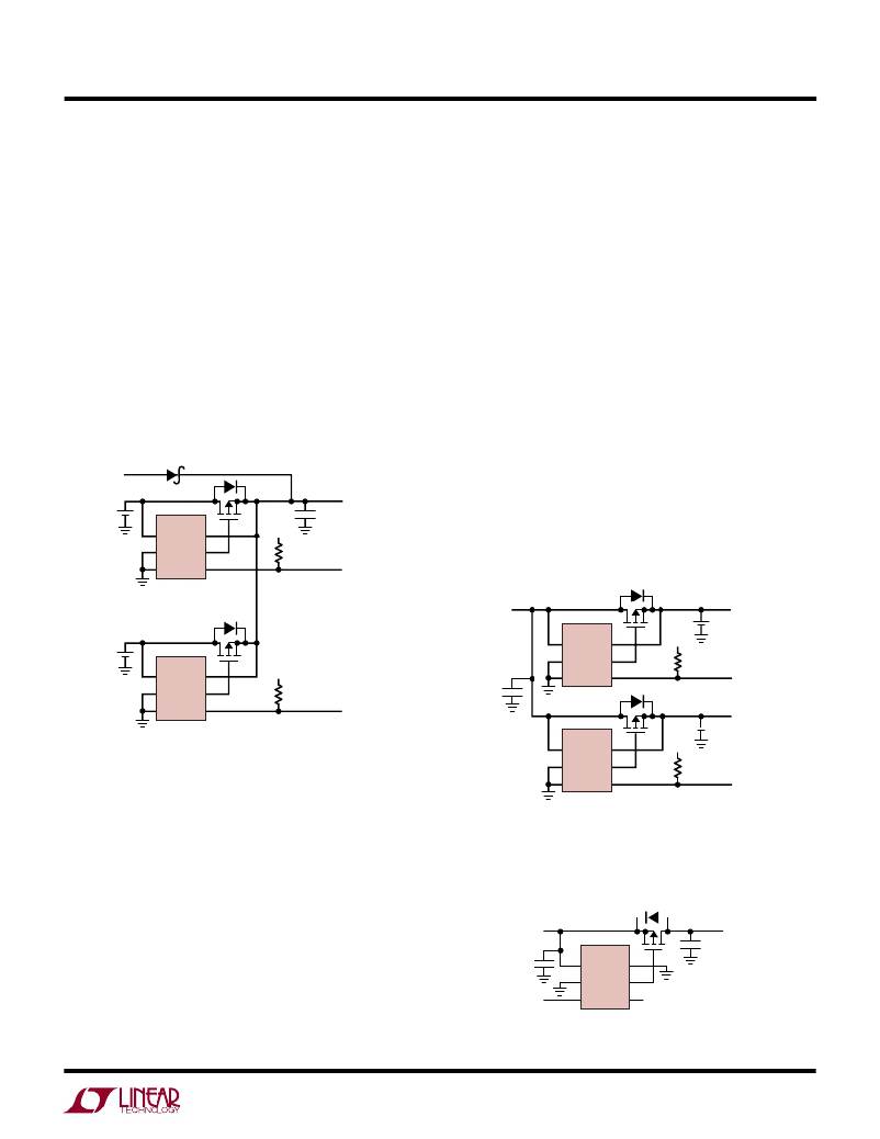
�Battery� Load� Sharing�
�Figure� 5� illustrates� an� application� circuit� for� dual� battery�
�load� sharing� with� automatic� switchover� of� load� from�
�batteries� to� wall� adapter.� Whichever� battery� can� supply� the�
�higher� voltage� will� provide� the� load� current� until� it� is�
�discharged� to� the� voltage� of� the� other� battery.� The� load� will�
�then� be� shared� between� the� two� batteries� according� to� the�
�capacity� of� each� battery.� The� higher� capacity� battery� will�
�provide� proportionally� higher� current� to� the� load.� When� a�
�wall� adapter� input� is� applied,� both� MOSFETs� will� turn� off�
�and� no� load� current� will� be� drawn� from� the� batteries.� The�
�STAT� pins� provide� information� as� to� which� input� is� supply-�
�ing� the� load� current.� This� concept� can� be� expanded� to�
�more� power� inputs.�
�WALL�
�ADAPTER�
�CTL� pin� input� can� be� used� with� a� microcontroller� and�
�back-to-back� MOSFETs� as� shown� in� Figure� 4.� This� allows�
�complete� control� for� disconnection� of� the� charger� from�
�either� battery.�
�High� Side� Power� Switch�
�Figure� 7� illustrates� an� application� circuit� for� a� logic� con-�
�trolled� high� side� power� switch.� When� the� CTL� pin� is� a�
�logical� low,� the� LTC4414� will� turn� on� the� MOSFET.� Be-�
�cause� the� SENSE� pin� is� grounded,� the� LTC4414� will� apply�
�maximum� clamped� gate� drive� voltage� to� the� MOSFET.�
�When� the� CTL� pin� is� a� logical� high,� the� LTC4414� will� turn�
�off� the� MOSFET� by� pulling� its� gate� voltage� up� to� the� supply�
�input� voltage� and� thus� deny� power� to� the� load.� The�
�MOSFET� is� connected� with� its� source� connected� to� the�
�power� source.� This� disables� the� drain-source� diode� from�
�INPUT�
�BAT1�
�7�
�3�
�2�
�LTC4414�
�V� IN� SENSE�
�GND� GATE�
�CTL� STAT�
�6�
�8�
�1�
�*�
�V� CC�
�47k�
�C� OUT�
�TO� LOAD�
�STATUS� IS� HIGH�
�WHEN� BAT1� IS�
�SUPPLYING�
�supplying� voltage� to� the� load� when� the� MOSFET� is� off.� Note�
�that� if� the� load� is� powered� from� another� source,� then� the�
�drain-source� diode� can� forward� bias� and� deliver� current� to�
�the� power� supply� connected� to� the� V� IN� pin.�
�LOAD� CURRENT�
�STATUS� IS� HIGH�
�SUPPLYING�
�BAT2�
�7�
�3�
�2�
�LTC4414�
�V� IN� SENSE�
�GND� GATE�
�CTL� STAT�
�6�
�8�
�1�
�*�
�WHEN� BOTH� STATUS� LINES� ARE�
�HIGH,� THEN� BOTH� BATTERIES� ARE�
�SUPPLYING� LOAD� CURRENTS.� WHEN�
�BOTH� STATUS� LINES� ARE� LOW,� THEN�
�WALL� ADAPTER� IS� PRESENT�
�V� CC�
�47k�
�WHEN� BAT2� IS�
�4414� F05�
�BATTERY�
�CHARGER�
�INPUT�
�0.1� μ� F�
�7�
�3�
�2�
�LTC4414�
�V� IN� SENSE�
�GND� GATE�
�CTL� STAT�
�6�
�8�
�1�
�*�
�*�
�V� CC�
�470k�
�TO� LOAD� OR�
�PowerPath�
�BAT1� CONTROLLER�
�STATUS� IS� HIGH�
�WHEN� BAT1� IS�
�CHARGING�
�TO� LOAD� OR�
�PowerPath�
�*DRAIN-SOURCE� DIODE� OF� MOSFET�
�CHARGING�
�LOAD� CURRENT�
�Figure� 5.� Dual� Battery� Load� Sharing� with� Automatic�
�Switchover� of� Load� from� Batteries� to� Wall� Adapter�
�7�
�3�
�2�
�LTC4414�
�V� IN� SENSE�
�GND� GATE�
�CTL� STAT�
�6�
�8�
�1�
�V� CC�
�470k�
�BAT2� CONTROLLER�
�STATUS� IS� HIGH�
�WHEN� BAT2� IS�
�4414� F06�
�Multiple� Battery� Charging�
�Figure� 6� illustrates� an� application� circuit� for� automatic�
�dual� battery� charging� from� a� single� charger.� Whichever�
�battery� has� the� lower� voltage� will� receive� the� charging�
�current� until� both� battery� voltages� are� equal,� then� both� will�
�*DRAIN-SOURCE� DIODE� OF� MOSFET�
�Figure� 6.� Automatic� Dual� Battery� Charging�
�from� Single� Charging� Source�
�P-CHANNEL�
�MOSFET�
�be� charged.� When� both� are� charged� simultaneously,� the�
�higher� capacity� battery� will� get� proportionally� higher� cur-�
�rent� from� the� charger.� For� Li-Ion� batteries,� both� batteries�
�will� achieve� the� float� voltage� minus� the� forward� regulation�
�voltage� of� 20mV.� This� concept� can� apply� to� more� than� two�
�SUPPLY�
�INPUT�
�0.1� μ� F�
�LOGIC�
�INPUT�
�7�
�3�
�2�
�LTC4414�
�V� IN� SENSE�
�GND� GATE�
�CTL� STAT�
�6�
�8�
�1�
�4414� F07�
�*�
�C� OUT�
�TO� LOAD�
�batteries.� The� STAT� pins� provide� information� as� to� which�
�batteries� are� being� charged.� For� intelligent� control,� the�
�*DRAIN-SOURCE� DIODE� OF� MOSFET�
�Figure� 7.� Logic� Controlled� High� Side� Power� Switch�
�4414fc�
�Information� furnished� by� Linear� Technology� Corporation� is� believed� to� be� accurate� and� reliable.�
�However,� no� responsibility� is� assumed� for� its� use.� Linear� Technology� Corporation� makes� no� represen-�
�tation� that� the� interconnection� of� its� circuits� as� described� herein� will� not� infringe� on� existing� patent� rights.�
�11�
�相关PDF资料 |
PDF描述 |
|---|---|
| GMA06DTAH | CONN EDGECARD 12POS R/A .125 SLD |
| VI-B6H-CW-F2 | CONVERTER MOD DC/DC 52V 100W |
| ES2A-13 | RECT SUPER FAST SMD 50V 2A SMB |
| 395-100-541-204 | CARD EDGE 100PS DL .100X.200 BLK |
| S120J25U2JR6BV7R | CAP CER 12PF 3KV 5% RADIAL |
相关代理商/技术参数 |
参数描述 |
|---|---|
| LTC4415EDHC#PBF | 功能描述:IC DUAL 4A DIODES 16-DFN RoHS:是 类别:集成电路 (IC) >> PMIC - O 圈控制器 系列:PowerPath™ 标准包装:1,000 系列:- 应用:电池备份,工业/汽车,大电流开关 FET 型:- 输出数:5 内部开关:是 延迟时间 - 开启:100ns 延迟时间 - 关闭:- 电源电压:3 V ~ 5.5 V 电流 - 电源:250µA 工作温度:0°C ~ 70°C 安装类型:表面贴装 封装/外壳:16-SOIC(0.154",3.90mm 宽) 供应商设备封装:16-SOIC N 包装:带卷 (TR) |
| LTC4415EDHC#TRPBF | 功能描述:IC DUAL 4A DIODES 16-DFN RoHS:是 类别:集成电路 (IC) >> PMIC - O 圈控制器 系列:PowerPath™ 标准包装:1,000 系列:- 应用:电池备份,工业/汽车,大电流开关 FET 型:- 输出数:5 内部开关:是 延迟时间 - 开启:100ns 延迟时间 - 关闭:- 电源电压:3 V ~ 5.5 V 电流 - 电源:250µA 工作温度:0°C ~ 70°C 安装类型:表面贴装 封装/外壳:16-SOIC(0.154",3.90mm 宽) 供应商设备封装:16-SOIC N 包装:带卷 (TR) |
| LTC4415EMSE#PBF | 功能描述:IC DUAL 4A DIODES 16-MSOP RoHS:是 类别:集成电路 (IC) >> PMIC - O 圈控制器 系列:PowerPath™ 标准包装:1,000 系列:- 应用:电池备份,工业/汽车,大电流开关 FET 型:- 输出数:5 内部开关:是 延迟时间 - 开启:100ns 延迟时间 - 关闭:- 电源电压:3 V ~ 5.5 V 电流 - 电源:250µA 工作温度:0°C ~ 70°C 安装类型:表面贴装 封装/外壳:16-SOIC(0.154",3.90mm 宽) 供应商设备封装:16-SOIC N 包装:带卷 (TR) |
| LTC4415EMSE#TRPBF | 功能描述:IC DUAL 4A DIODES 16-MSOP RoHS:是 类别:集成电路 (IC) >> PMIC - O 圈控制器 系列:PowerPath™ 标准包装:1,000 系列:- 应用:电池备份,工业/汽车,大电流开关 FET 型:- 输出数:5 内部开关:是 延迟时间 - 开启:100ns 延迟时间 - 关闭:- 电源电压:3 V ~ 5.5 V 电流 - 电源:250µA 工作温度:0°C ~ 70°C 安装类型:表面贴装 封装/外壳:16-SOIC(0.154",3.90mm 宽) 供应商设备封装:16-SOIC N 包装:带卷 (TR) |
| LTC4415IDHC#PBF | 功能描述:IC DUAL 4A DIODES 16-DFN RoHS:是 类别:集成电路 (IC) >> PMIC - O 圈控制器 系列:PowerPath™ 标准包装:1,000 系列:- 应用:电池备份,工业/汽车,大电流开关 FET 型:- 输出数:5 内部开关:是 延迟时间 - 开启:100ns 延迟时间 - 关闭:- 电源电压:3 V ~ 5.5 V 电流 - 电源:250µA 工作温度:0°C ~ 70°C 安装类型:表面贴装 封装/外壳:16-SOIC(0.154",3.90mm 宽) 供应商设备封装:16-SOIC N 包装:带卷 (TR) |
发布紧急采购,3分钟左右您将得到回复。