- 您现在的位置:买卖IC网 > PDF目录68607 > M306K7F8LRP 16-BIT, FLASH, 8 MHz, MICROCONTROLLER, PQFP144 PDF资料下载
参数资料
| 型号: | M306K7F8LRP |
| 元件分类: | 微控制器/微处理器 |
| 英文描述: | 16-BIT, FLASH, 8 MHz, MICROCONTROLLER, PQFP144 |
| 封装: | PLASTIC, QFP-144 |
| 文件页数: | 268/284页 |
| 文件大小: | 2906K |
| 代理商: | M306K7F8LRP |
第1页第2页第3页第4页第5页第6页第7页第8页第9页第10页第11页第12页第13页第14页第15页第16页第17页第18页第19页第20页第21页第22页第23页第24页第25页第26页第27页第28页第29页第30页第31页第32页第33页第34页第35页第36页第37页第38页第39页第40页第41页第42页第43页第44页第45页第46页第47页第48页第49页第50页第51页第52页第53页第54页第55页第56页第57页第58页第59页第60页第61页第62页第63页第64页第65页第66页第67页第68页第69页第70页第71页第72页第73页第74页第75页第76页第77页第78页第79页第80页第81页第82页第83页第84页第85页第86页第87页第88页第89页第90页第91页第92页第93页第94页第95页第96页第97页第98页第99页第100页第101页第102页第103页第104页第105页第106页第107页第108页第109页第110页第111页第112页第113页第114页第115页第116页第117页第118页第119页第120页第121页第122页第123页第124页第125页第126页第127页第128页第129页第130页第131页第132页第133页第134页第135页第136页第137页第138页第139页第140页第141页第142页第143页第144页第145页第146页第147页第148页第149页第150页第151页第152页第153页第154页第155页第156页第157页第158页第159页第160页第161页第162页第163页第164页第165页第166页第167页第168页第169页第170页第171页第172页第173页第174页第175页第176页第177页第178页第179页第180页第181页第182页第183页第184页第185页第186页第187页第188页第189页第190页第191页第192页第193页第194页第195页第196页第197页第198页第199页第200页第201页第202页第203页第204页第205页第206页第207页第208页第209页第210页第211页第212页第213页第214页第215页第216页第217页第218页第219页第220页第221页第222页第223页第224页第225页第226页第227页第228页第229页第230页第231页第232页第233页第234页第235页第236页第237页第238页第239页第240页第241页第242页第243页第244页第245页第246页第247页第248页第249页第250页第251页第252页第253页第254页第255页第256页第257页第258页第259页第260页第261页第262页第263页第264页第265页第266页第267页当前第268页第269页第270页第271页第272页第273页第274页第275页第276页第277页第278页第279页第280页第281页第282页第283页第284页
Timer A
Mitsubishi microcomputers
M16C / 6K7 Group
SINGLE-CHIP 16-BIT CMOS MICROCOMPUTER
84
Rev.1.0
(4) Pulse width modulation (PWM) mode
In this mode, the timer outputs pulses of a given width in succession. (See Table.FB-5) In this mode, the
counter functions as either a 16-bit pulse width modulator or an 8-bit pulse width modulator. Fig.FB-11
shows the timer Ai mode register in pulse width modulation mode. Fig.FB-12 shows the example of how a
16-bit pulse width modulator operates. Fig.FB-13 shows the example of how an 8-bit pulse width modulator
operates.
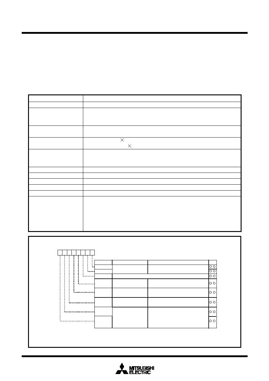
Fig.FB-11 Timer Ai mode register in pulse width modulation mode
Table.FB-5 Timer specifications in pulse width modulation mode
Bit name
Timer Ai mode register
Symbol
Address
When reset
TAiMR(i=0 to 4)
039616 to 039A16
0016
Function
Bit symbol
b7
b6
b5
b4
b3
b2
b1
b0
Operation mode selection
bits
1 1 : PWM mode
b1 b0
TMOD1
TMOD0
MR0
MR2
MR1
MR3
0 0 : f1
0 1 : f8
1 0 : f32
1 1 : fC32
b7 b6
TCK1
TCK0
Count source selection bits
W
R
11
1
1 (Must always be “1” in PWM mode)
16/8-bit PWM mode
selection bit
0: Functions as a 16-bit pulse width modulator
1: Functions as an 8-bit pulse width modulator
Trigger selection bit
External trigger selection
bit (Note 1)
0: Falling edge of TAiIN pin's input signal (Note 2)
1: Rising edge of TAiIN pin's input signal (Note 2)
0: Count start flag is valid
1: Selected by event/trigger selection register
Note 1: Valid only when the TAiIN pin is selected by the event/trigger selection bit
(addresses 038216 and 038316). If timer overflow is selected, this bit can be “1” or “0”.
Note 2: Set the corresponding port direction register to “0”.
Item
Specification
Count source
f1, f8, f32, fC32
Count operation
The timer counts down (operating as an 8-bit or a 16-bit pulse width modulator)
The timer reloads a new count at a rising edge of PWM pulse and continues counting
The timer is not affected by a trigger that occurs when counting
16-bit PWM
High level width
n / fi
n : Set value
Cycle time
(216-1) / fi fixed
8-bit PWM
High level width n (m+1) / fi
n : values set to timer Ai register’s high-order address
Cycle time
(28-1) (m+1) / fi
m : values set to timer Ai register’s low-order address
Count start condition
External trigger is input
The timer overflows
The count start flag is set (= 1)
Count stop condition
The count start flag is reset (= 0)
Interrupt request generation timing
The falling edge of PWM pulse
TAiIN pin function
Programmable I/O port or trigger input
TAiOUT pin function
Pulse output
Read from timer
When timer Ai register is read, it indicates an indeterminate value
Write to timer
When counting stopped
When a value is written to timer Ai register, it is written to both reload
register and counter
When counting in progress
When a value is written to timer Ai register, it is written to only reload register
(Transferred to counter at next reload time)
相关PDF资料 |
PDF描述 |
|---|---|
| M35052-001FP | 24 X 10 CHARACTERS CRT CHAR DSPL CTLR, PDSO20 |
| MAX6826LUT+T | Dual, Ultra-Low-Voltage SOT23 µP Supervisors with Manual Reset and Watchdog Timer |
| MAX6826MUT+T | Dual, Ultra-Low-Voltage SOT23 µP Supervisors with Manual Reset and Watchdog Timer |
| MAX6826RUT+T | Dual, Ultra-Low-Voltage SOT23 µP Supervisors with Manual Reset and Watchdog Timer |
| MAX6826SUT+T | Dual, Ultra-Low-Voltage SOT23 µP Supervisors with Manual Reset and Watchdog Timer |
相关代理商/技术参数 |
参数描述 |
|---|---|
| M306K9FCLRP | 制造商:RENESAS 制造商全称:Renesas Technology Corp 功能描述:SINGLE-CHIP 16-BIT CMOS MICROCOMPUTER |
| M306K9T2-CPE | 功能描述:M-SUPPORT TOOL RoHS:否 类别:编程器,开发系统 >> 内电路编程器、仿真器以及调试器 系列:- 产品变化通告:Development Systems Discontinuation 19/Jul/2010 标准包装:1 系列:* 类型:* 适用于相关产品:* 所含物品:* |
| M306KAFCLRP | 制造商:RENESAS 制造商全称:Renesas Technology Corp 功能描述:SINGLE-CHIP 16-BIT CMOS MICROCOMPUTER Description |
| M306N0FG | 制造商:MITSUBISHI 制造商全称:Mitsubishi Electric Semiconductor 功能描述:SINGLE-CHIP 16-BIT CMOS MICROCOMPUTER |
| M306N0FGT | 制造商:MITSUBISHI 制造商全称:Mitsubishi Electric Semiconductor 功能描述:SINGLE-CHIP 16-BIT CMOS MICROCOMPUTER |
发布紧急采购,3分钟左右您将得到回复。