参数资料
| 型号: | MAX1400CAI+ |
| 厂商: | Maxim Integrated Products |
| 文件页数: | 13/34页 |
| 文件大小: | 0K |
| 描述: | IC ADC 18BIT LP 28-SSOP |
| 产品培训模块: | Lead (SnPb) Finish for COTS Obsolescence Mitigation Program |
| 标准包装: | 46 |
| 位数: | 18 |
| 采样率(每秒): | 480 |
| 数据接口: | QSPI?,串行,SPI? |
| 转换器数目: | 1 |
| 功率耗散(最大): | 1.25mW |
| 电压电源: | 模拟和数字 |
| 工作温度: | 0°C ~ 70°C |
| 安装类型: | 表面贴装 |
| 封装/外壳: | 28-SSOP(0.209",5.30mm 宽) |
| 供应商设备封装: | 28-SSOP |
| 包装: | 管件 |
| 输入数目和类型: | 3 个差分,单极;3 个差分,双极;5 个伪差分,单极;5 个伪差分,双极 |
第1页第2页第3页第4页第5页第6页第7页第8页第9页第10页第11页第12页当前第13页第14页第15页第16页第17页第18页第19页第20页第21页第22页第23页第24页第25页第26页第27页第28页第29页第30页第31页第32页第33页第34页
MAX1400
+5V, 18-Bit, Low-Power, Multichannel,
Oversampling (Sigma-Delta) ADC
20
______________________________________________________________________________________
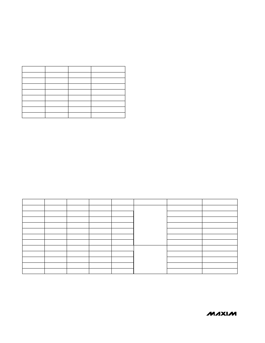
Table 11. Channel ID Tag Codes
Switching Network
A switching network provides selection between three
fully differential input channels or five pseudo-differen-
tial channels, using AIN6 as a shared common. The
switching network provides two additional fully differen-
tial input channels intended for system calibration,
which may be used as extra fully differential signal
channels. Table 12 shows the channel configurations
available for both operating modes.
Scanning (SCAN-mode)
To sample and convert the available input channels
sequentially, set the SCAN control bit in the global
setup register. The sequence is determined by DIFF
(fully differential or pseudo-differential) and by the
mode control bits M1 and M0 (Tables 8, 9, 10). With
SCAN set, the part automatically sequences through
each available channel, transmitting a single conver-
sion result before proceeding to the next channel. The
MAX1400 automatically allows sufficient time for each
conversion to fully settle, to ensure optimum resolution
before asserting the data-ready signal and moving to
the next available channel. The scan rate is, therefore,
dependent on the clock bit (CLK), the filter control bits
(FS1, FS0), and the modulator frequency selection bits
(MF1, MF0).
Burnout Currents
The input circuitry also provides two “burnout” currents.
These small currents may be used to test the integrity
of the selected transducer. They can be selectively
enabled or disabled by the BOUT bit in the global
setup register.
CHANNEL
CID2
1
AIN1–AIN2
AIN5–AIN6
1
Calibration
1
0
1
AIN3–AIN4
1
0
AIN1–AIN6
AIN3–AIN6
0
AIN4–AIN6
1
0
1
0
AIN2–AIN6
1
0
CID0
0
CID1
0
Table 12. Input Channel Configuration in Fully and Pseudo-Differential Modes
(SCAN = 0)
X = Don’t Care.
* This combination is available only in pseudo-differential mode when using the internal scanning logic
** These combinations are only available in the calibration modes.
0
M0
0
DIFF
0
AIN2
0
AIN4
0
AIN3
AIN1
0
1
0
1
AIN3
0
1
X
CALOFF+**
0
AIN5
AIN1
0
X
1
X
CALOFF+**
M1
0
X
HIGH INPUT
CALGAIN+**
AIN5*
1
0
X
CALGAIN+**
1
0
A1
0
1
0
1
X
MODE
Pseudo-
Differential
Fully
Differential
0
A0
1
0
1
0
1
0
X
AIN6
AIN4
CALOFF-**
AIN6
AIN2
CALOFF-**
LOW INPUT
CALGAIN-**
AIN6*
CALGAIN-**
相关PDF资料 |
PDF描述 |
|---|---|
| MAX1401CAI+ | IC ADC 18BIT LP 28-SSOP |
| MAX1415AEWE+T | IC ADC 16BIT DELTA SIGMA 16-SOIC |
| MAX1421CCM+D | IC ADC 12BIT 40MSPS 48LQFP |
| MAX1426EAI+T | IC ADC 10BITS 10MSPS 28SSOP |
| MAX1434ECQ+D | IC ADC 10BIT 50MSPS 100-TQFP |
相关代理商/技术参数 |
参数描述 |
|---|---|
| MAX1400CAI+ | 功能描述:模数转换器 - ADC 18-Bit 5Ch 4.8ksps 2.5V Precision ADC RoHS:否 制造商:Texas Instruments 通道数量:2 结构:Sigma-Delta 转换速率:125 SPs to 8 KSPs 分辨率:24 bit 输入类型:Differential 信噪比:107 dB 接口类型:SPI 工作电源电压:1.7 V to 3.6 V, 2.7 V to 5.25 V 最大工作温度:+ 85 C 安装风格:SMD/SMT 封装 / 箱体:VQFN-32 |
| MAX1400CAI+T | 功能描述:模数转换器 - ADC 18-Bit 5Ch 4.8ksps 2.5V Precision ADC RoHS:否 制造商:Texas Instruments 通道数量:2 结构:Sigma-Delta 转换速率:125 SPs to 8 KSPs 分辨率:24 bit 输入类型:Differential 信噪比:107 dB 接口类型:SPI 工作电源电压:1.7 V to 3.6 V, 2.7 V to 5.25 V 最大工作温度:+ 85 C 安装风格:SMD/SMT 封装 / 箱体:VQFN-32 |
| MAX1400CAI+W | 制造商:Maxim Integrated Products 功能描述: |
| MAX1400CAI-T | 功能描述:模数转换器 - ADC RoHS:否 制造商:Texas Instruments 通道数量:2 结构:Sigma-Delta 转换速率:125 SPs to 8 KSPs 分辨率:24 bit 输入类型:Differential 信噪比:107 dB 接口类型:SPI 工作电源电压:1.7 V to 3.6 V, 2.7 V to 5.25 V 最大工作温度:+ 85 C 安装风格:SMD/SMT 封装 / 箱体:VQFN-32 |
| MAX1400EAI | 功能描述:模数转换器 - ADC RoHS:否 制造商:Texas Instruments 通道数量:2 结构:Sigma-Delta 转换速率:125 SPs to 8 KSPs 分辨率:24 bit 输入类型:Differential 信噪比:107 dB 接口类型:SPI 工作电源电压:1.7 V to 3.6 V, 2.7 V to 5.25 V 最大工作温度:+ 85 C 安装风格:SMD/SMT 封装 / 箱体:VQFN-32 |
发布紧急采购,3分钟左右您将得到回复。