参数资料
| 型号: | MAX1400CAI+ |
| 厂商: | Maxim Integrated Products |
| 文件页数: | 20/34页 |
| 文件大小: | 0K |
| 描述: | IC ADC 18BIT LP 28-SSOP |
| 产品培训模块: | Lead (SnPb) Finish for COTS Obsolescence Mitigation Program |
| 标准包装: | 46 |
| 位数: | 18 |
| 采样率(每秒): | 480 |
| 数据接口: | QSPI?,串行,SPI? |
| 转换器数目: | 1 |
| 功率耗散(最大): | 1.25mW |
| 电压电源: | 模拟和数字 |
| 工作温度: | 0°C ~ 70°C |
| 安装类型: | 表面贴装 |
| 封装/外壳: | 28-SSOP(0.209",5.30mm 宽) |
| 供应商设备封装: | 28-SSOP |
| 包装: | 管件 |
| 输入数目和类型: | 3 个差分,单极;3 个差分,双极;5 个伪差分,单极;5 个伪差分,双极 |
第1页第2页第3页第4页第5页第6页第7页第8页第9页第10页第11页第12页第13页第14页第15页第16页第17页第18页第19页当前第20页第21页第22页第23页第24页第25页第26页第27页第28页第29页第30页第31页第32页第33页第34页
MAX1400
+5V, 18-Bit, Low-Power, Multichannel,
Oversampling (Sigma-Delta) ADC
______________________________________________________________________________________
27
Digital Filter
The on-chip digital filter processes the 1-bit data
stream from the modulator using a SINC3 or SINC3 fil-
ter. The SINC filters are conceptually simple, efficient,
and extremely flexible, especially where variable reso-
lution and data rates are required. Also, the filter notch
positions are easily controlled, since they are directly
related to the output data rate (1 / data word period).
The SINC1 function results in a faster settling response
while retaining the same frequency response notches
as the default SINC3 filter. This allows the filter to settle
faster at the expense of resolution and quantization
noise. The SINC1 filter settles in one data word period.
With 60Hz notches (60Hz data rate), the settling time
would be 1 / 60Hz or 16.7ms whereas the SINC3 filter
would settle in 3 / 60Hz or 50ms. Toggle between these
filter responses using the FAST bit in the global setup
register. Use SINC1 mode for faster settling and switch
to SINC3 mode when full accuracy is required. Switch
from the SINC1 to SINC3 mode by resetting the FAST
bit low. The DRDY signal will go false and will be
reasserted when valid data is available, a minimum of
three data-word periods later.
The digital filter can be bypassed by setting the MDOUT
bit in the global setup register. When MDOUT = 1, the
raw output of the modulator is directly available at
DOUT.
Filter Characteristics
The MAX1400 digital filter implements both a SINC1
(sinx/x) and SINC3 (sinx/x)3 lowpass filter function. The
transfer function for the SINC3 function is that of three
cascaded SINC1 filters described in the z-domain by:
and in the frequency domain by:
where N, the decimation factor, is the ratio of the modu-
lator frequency fM to the output frequency fN.
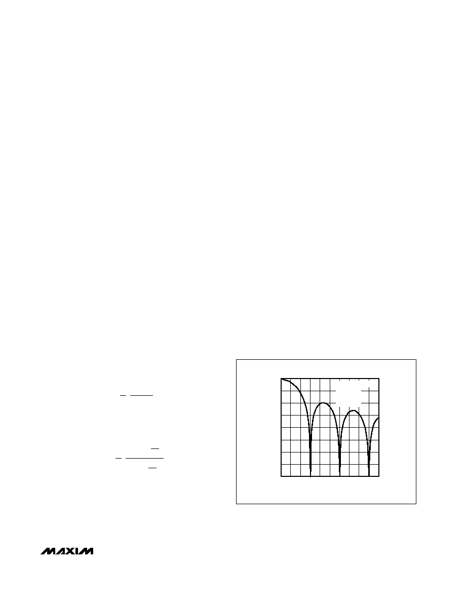
Figure 10 shows the filter frequency response. The
SINC3 characteristic cutoff frequency is 0.262 times the
first notch frequency. This results in a cutoff frequency
of 15.72Hz for a first filter notch frequency of 60Hz. The
response shown in Figure 10 is repeated at either side
of the digital filter’s sample frequency (fM) and at either
side of the related harmonics (2fM, 3fM, . . .).
The response of the SINC3 filter is similar to that of a
SINC1 (averaging filter) filter but with a sharper rolloff.
The output data rate for the digital filter corresponds
with the positioning of the first notch of the filter’s fre-
quency response. Therefore, for the plot of Figure 10
where the first notch of the filter is at 60Hz, the output
data rate is 60Hz. The notches of this (sinx/x)3 filter are
repeated at multiples of the first notch frequency. The
SINC3 filter provides an attenuation of better than
100dB at these notches.
Determine the cutoff frequency of the digital filter by the
value loaded into CLK, X2CLK, MF1, MF0, FS1, and
FS0 in the global setup register. Programming a differ-
ent cutoff frequency with FS0 and FS1 does not alter
the profile of the filter response; it changes the frequen-
cy of the notches. For example, Figure 11 shows a cut-
off frequency of 13.1Hz and a first notch frequency of
50Hz.
For step changes at the input, a settling time must be
allowed before valid data can be read. The settling time
depends upon the output data rate chosen for the filter.
The settling time of the SINC3 filter to a full-scale step
H(f)
1
N
sin Np
f
sin p
f
M
3
=
H(z)
1
N
1z
N
1
3
=
-160
-120
-140
-100
-80
-60
-20
-40
0
406080
20
100 120 140 160 180 200
FREQUENCY (Hz)
GAIN
(dB)
fCLKIN = 2.4576MHz
MF1, 0 = 0
FS1, 0 = 1
fN = 60Hz
Figure 10. Frequency Response of the SINC3 Filter (Notch at
60Hz)
相关PDF资料 |
PDF描述 |
|---|---|
| MAX1401CAI+ | IC ADC 18BIT LP 28-SSOP |
| MAX1415AEWE+T | IC ADC 16BIT DELTA SIGMA 16-SOIC |
| MAX1421CCM+D | IC ADC 12BIT 40MSPS 48LQFP |
| MAX1426EAI+T | IC ADC 10BITS 10MSPS 28SSOP |
| MAX1434ECQ+D | IC ADC 10BIT 50MSPS 100-TQFP |
相关代理商/技术参数 |
参数描述 |
|---|---|
| MAX1400CAI+ | 功能描述:模数转换器 - ADC 18-Bit 5Ch 4.8ksps 2.5V Precision ADC RoHS:否 制造商:Texas Instruments 通道数量:2 结构:Sigma-Delta 转换速率:125 SPs to 8 KSPs 分辨率:24 bit 输入类型:Differential 信噪比:107 dB 接口类型:SPI 工作电源电压:1.7 V to 3.6 V, 2.7 V to 5.25 V 最大工作温度:+ 85 C 安装风格:SMD/SMT 封装 / 箱体:VQFN-32 |
| MAX1400CAI+T | 功能描述:模数转换器 - ADC 18-Bit 5Ch 4.8ksps 2.5V Precision ADC RoHS:否 制造商:Texas Instruments 通道数量:2 结构:Sigma-Delta 转换速率:125 SPs to 8 KSPs 分辨率:24 bit 输入类型:Differential 信噪比:107 dB 接口类型:SPI 工作电源电压:1.7 V to 3.6 V, 2.7 V to 5.25 V 最大工作温度:+ 85 C 安装风格:SMD/SMT 封装 / 箱体:VQFN-32 |
| MAX1400CAI+W | 制造商:Maxim Integrated Products 功能描述: |
| MAX1400CAI-T | 功能描述:模数转换器 - ADC RoHS:否 制造商:Texas Instruments 通道数量:2 结构:Sigma-Delta 转换速率:125 SPs to 8 KSPs 分辨率:24 bit 输入类型:Differential 信噪比:107 dB 接口类型:SPI 工作电源电压:1.7 V to 3.6 V, 2.7 V to 5.25 V 最大工作温度:+ 85 C 安装风格:SMD/SMT 封装 / 箱体:VQFN-32 |
| MAX1400EAI | 功能描述:模数转换器 - ADC RoHS:否 制造商:Texas Instruments 通道数量:2 结构:Sigma-Delta 转换速率:125 SPs to 8 KSPs 分辨率:24 bit 输入类型:Differential 信噪比:107 dB 接口类型:SPI 工作电源电压:1.7 V to 3.6 V, 2.7 V to 5.25 V 最大工作温度:+ 85 C 安装风格:SMD/SMT 封装 / 箱体:VQFN-32 |
发布紧急采购,3分钟左右您将得到回复。