- 您现在的位置:买卖IC网 > PDF目录15488 > MAX1858EEG+ (Maxim Integrated Products)IC REG CTRLR BUCK PWM VM 24-QSOP PDF资料下载
参数资料
| 型号: | MAX1858EEG+ |
| 厂商: | Maxim Integrated Products |
| 文件页数: | 14/21页 |
| 文件大小: | 0K |
| 描述: | IC REG CTRLR BUCK PWM VM 24-QSOP |
| 产品培训模块: | Lead (SnPb) Finish for COTS Obsolescence Mitigation Program |
| 标准包装: | 50 |
| PWM 型: | 电压模式 |
| 输出数: | 2 |
| 频率 - 最大: | 660kHz |
| 占空比: | 90% |
| 电源电压: | 4.75 V ~ 23 V |
| 降压: | 是 |
| 升压: | 无 |
| 回扫: | 无 |
| 反相: | 无 |
| 倍增器: | 无 |
| 除法器: | 无 |
| Cuk: | 无 |
| 隔离: | 无 |
| 工作温度: | -40°C ~ 85°C |
| 封装/外壳: | 24-SSOP(0.154",3.90mm 宽) |
| 包装: | 管件 |
�� �
�
�Dual� 180°� Out-of-Phase� PWM� Step-Down�
�Controller� with� Power� Sequencing� and� POR�
�Connect� ILIM_� to� V� L� for� the� default� 100mV� (typ)� current-�
�limit� threshold.� For� an� adjustable� threshold,� connect� a�
�resistor� (R� ILIM� _)� from� ILIM_� to� GND.� The� relationship�
�between� the� current-limit� threshold� (V� ITH� _)� and� R� ILIM� _� is:�
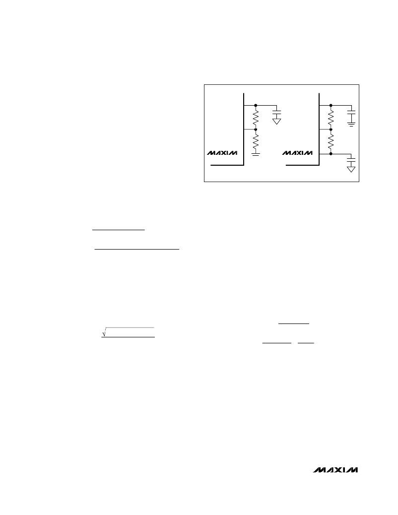
�OUT_�
�R_A�
�REF�
�R_C�
�R� ILIM� _� =�
�V� ITH� _�
�0� .� 5� μ� A�
�FB_�
�FB_�
�where� R� ILIM� _� is� in� ?� and� V� ITH� _� is� in� V.� An� R� ILIM� resis-�
�tance� range� of� 100k� ?� to� 600k� ?� corresponds� to� a� current-�
�limit� threshold� of� 50mV� to� 300mV.� When� adjusting� the�
�current� limit,� 1%� tolerance� resistors� minimizes� error� in� the�
�current-limit� threshold.� For� foldback� current� limit,� a� resis-�
�tor� (R� FBI� )� is� added� from� ILIM� pin� to� output.� The� value� of�
�MAX1858�
�V� OUT_� >� 1V�
�R_B�
�MAX1858�
�V� OUT_� <� 1V�
�R_A�
�OUT_�
�R� FBI� =�
�R� ILIM� =�
�10� � V� ITH� (� 1� -� P� FB� )� � R� FBI�
�[� V� OUT� -� 10� � V� ITH� (� 1� -� P� FB� )]�
�I� RMS� =� I� LOAD�
�V� RIPPLE� (� C� )� =�
�I� P� -� P� =� ?� IN� OUT� ?� ?� OUT� ?�
�R� ILIM� and� R� FBI� can� then� be� calculated� as� follows:�
�First� select� the� percentage� of� foldback� (P� FB� )� from� 15%�
�to� 30%,� then:�
�P� FB� � V� OUT�
�5� � 10� -� 6� (� 1� -� P� FB� )�
�and�
�Input� Capacitor�
�The� input� filter� capacitor� reduces� peak� currents� drawn�
�from� the� power� source� and� reduces� noise� and� voltage�
�ripple� on� the� input� caused� by� the� circuit� ’� s� switching.�
�The� input� capacitor� must� meet� the� ripple� current�
�requirement� (I� RMS� )� imposed� by� the� switching� currents�
�as� defined� by� the� following� equation:�
�V� OUT� (� V� IN� -� V� OUT� )�
�V� IN�
�I� RMS� has� a� maximum� value� when� the� input� voltage�
�equals� twice� the� output� voltage� (V� IN� =� 2V� OUT� ),� so�
�I� RMS(MAX)� =� I� LOAD� /� 2.� For� most� applications,� nontanta-�
�lum� capacitors� (ceramic,� aluminum,� polymer,� or�
�OSCON)� are� preferred� at� the� input� due� to� their� robust-�
�ness� with� high� inrush� currents� typical� of� systems� that� can�
�be� powered� from� very� low� impedance� sources.�
�Additionally,� two� (or� more)� smaller-value� low-ESR� capaci-�
�tors� can� be� connected� in� parallel� for� lower� cost.� Choose�
�an� input� capacitor� that� exhibits� less� than� +10� °� C� tem-�
�perature� rise� at� the� RMS� input� current� for� optimal� long-�
�term� reliability.�
�Figure� 6.� Adjustable� Output� Voltage�
�Output� Capacitor�
�The� key� selection� parameters� for� the� output� capacitor�
�are� capacitance� value,� ESR,� and� voltage� rating.� These�
�parameters� affect� the� overall� stability,� output� ripple� volt-�
�age,� and� transient� response.� The� output� ripple� has� two�
�components:� variations� in� the� charge� stored� in� the� out-�
�put� capacitor,� and� the� voltage� drop� across� the� capaci-�
�tor� ’� s� ESR� caused� by� the� current� flowing� in� to� and� out� of�
�the� capacitor.�
�V� RIPPLE� ?� V� RIPPLE� (� ESR� )� +� V� RIPPLE� (� C� )�
�The� output� voltage� ripple� as� a� consequence� of� the� ESR�
�and� output� capacitance� is:�
�V� RIPPLE� (� ESR� )� =� I� P� -� P� R� ESR�
�I� P� -� P�
�8� C� OUT� f� SW�
�?� V� -� V� ?� ?� V� ?�
�?� f� SW� L� ?� ?� V� IN� ?�
�where� I� P-P� is� the� peak-to-peak� inductor� current� (see� the�
�Inductor� Selection� section).� These� equations� are� suitable�
�for� initial� capacitor� selection,� but� final� values� should� be�
�verified� by� testing� in� a� prototype� or� evaluation� circuit.�
�As� a� general� rule,� a� smaller� inductor� ripple� current�
�results� in� less� output� ripple� voltage.� Since� inductor� rip-�
�ple� current� depends� on� the� inductor� value� and� input�
�voltage,� the� output� ripple� voltage� decreases� with� larger�
�inductance� and� increases� with� higher� input� voltages.�
�However,� the� inductor� ripple� current� also� impacts� tran-�
�sient-response� performance,� especially� at� low�
�V� IN� -� V� OUT� differentials.� Low� inductor� values� allow� the�
�inductor� current� to� slew� faster,� replenishing� charge�
�14�
�______________________________________________________________________________________�
�相关PDF资料 |
PDF描述 |
|---|---|
| MAX772ESA+ | IC REG CTRLR BST PWM 8-SOIC |
| MAX1744AUB+ | IC REG CTRLR BUCK PWM 10-UMAX |
| GBC30DRYN-S93 | CONN EDGECARD 60POS DIP .100 SLD |
| GBC35DRYI-S93 | CONN EDGECARD 70POS DIP .100 SLD |
| MAX1962EEP+ | IC REG CTRLR BUCK PWM VM 20-QSOP |
相关代理商/技术参数 |
参数描述 |
|---|---|
| MAX1858EEG+ | 功能描述:电压模式 PWM 控制器 Dual 180 Out Buck Controllers RoHS:否 制造商:Texas Instruments 输出端数量:1 拓扑结构:Buck 输出电压:34 V 输出电流: 开关频率: 工作电源电压:4.5 V to 5.5 V 电源电流:600 uA 最大工作温度:+ 125 C 最小工作温度:- 40 C 封装 / 箱体:WSON-8 封装:Reel |
| MAX1858EEG+T | 功能描述:电压模式 PWM 控制器 Dual 180 Out Buck Controllers RoHS:否 制造商:Texas Instruments 输出端数量:1 拓扑结构:Buck 输出电压:34 V 输出电流: 开关频率: 工作电源电压:4.5 V to 5.5 V 电源电流:600 uA 最大工作温度:+ 125 C 最小工作温度:- 40 C 封装 / 箱体:WSON-8 封装:Reel |
| MAX1858EEG-T | 功能描述:DC/DC 开关控制器 RoHS:否 制造商:Texas Instruments 输入电压:6 V to 100 V 开关频率: 输出电压:1.215 V to 80 V 输出电流:3.5 A 输出端数量:1 最大工作温度:+ 125 C 安装风格: 封装 / 箱体:CPAK |
| MAX1858EVKIT | 功能描述:DC/DC 开关控制器 Evaluation Kit for the MAX1858 MAX1875 MAX1876 RoHS:否 制造商:Texas Instruments 输入电压:6 V to 100 V 开关频率: 输出电压:1.215 V to 80 V 输出电流:3.5 A 输出端数量:1 最大工作温度:+ 125 C 安装风格: 封装 / 箱体:CPAK |
| MAX185ACNG | 功能描述:模数转换器 - ADC RoHS:否 制造商:Texas Instruments 通道数量:2 结构:Sigma-Delta 转换速率:125 SPs to 8 KSPs 分辨率:24 bit 输入类型:Differential 信噪比:107 dB 接口类型:SPI 工作电源电压:1.7 V to 3.6 V, 2.7 V to 5.25 V 最大工作温度:+ 85 C 安装风格:SMD/SMT 封装 / 箱体:VQFN-32 |
发布紧急采购,3分钟左右您将得到回复。