- 您现在的位置:买卖IC网 > PDF目录16545 > MAX5042ATN+T (Maxim Integrated Products)IC PWR W/MOSFET HS 56-TQFN PDF资料下载
参数资料
| 型号: | MAX5042ATN+T |
| 厂商: | Maxim Integrated Products |
| 文件页数: | 17/22页 |
| 文件大小: | 0K |
| 描述: | IC PWR W/MOSFET HS 56-TQFN |
| 产品培训模块: | Lead (SnPb) Finish for COTS Obsolescence Mitigation Program |
| 标准包装: | 2,500 |
| 应用: | 电源 |
| 电源电压: | 20 V ~ 76 V |
| 工作温度: | -40°C ~ 125°C |
| 安装类型: | 表面贴装 |
| 封装/外壳: | 56-WFQFN 裸露焊盘 |
| 供应商设备封装: | 56-TQFN-EP(8x8) |
| 包装: | 带卷 (TR) |
�� �
�
�Two-Switch� Power� ICs� with� Integrated�
�Power� MOSFETs� and� Hot-Swap� Controller�
�Maximize� the� signal-to-noise� ratio� by� setting� the� ramp�
�peak� as� high� as� possible.� Calculate� the� low-frequency,�
�small-signal� gain� of� the� power� stage� (the� gain� from� the�
�inverting� input� of� the� PWM� comparator� to� the� output)�
�using� the� following� formula:�
�G� PS� =� N� SP� ?� R� RCFF� ?� C� RCFF� ?� f� S�
�where� N� SP� =� the� secondary� to� primary� power� transformer�
�Oscillator� and� Synchronization�
�Program� the� MAX5042/MAX5043� oscillator� using� an� RC�
�network� at� RCOSC� with� the� resistor� connected� to� REG5�
�and� the� capacitor� connected� to� PWMNEG.� The� PWM�
�frequency� is� half� the� frequency� at� RCOSC.�
�Use� the� following� formula� to� calculate� the� oscillator�
�components:�
�2� f� S� (� C� RCOSC� +� C� PCB� )� ln� ?�
�?� V� REG� 5� ?� V� TH� ?�
�turns� ratio.�
�Current-Sense� Amplifier� and� Current-Mode� Control�
�The� MAX5042/MAX5043� can� also� be� programmed� for�
�current-mode� control� (see� Figure� 6).� This� control�
�R� RCOSC� =�
�1�
�?� V� REG� 5� ?�
�?�
�G� PS� PS� �
�=� N�
�method� offers� beneficial� advantages� for� certain� appli-�
�cations.� Current-mode� control� reduces� the� order� of� the�
�output� filter,� allowing� easier� control-loop� compensation.�
�In� current-mode� control,� the� voltage� across� the� current-�
�sense� resistor� at� SRC� is� amplified� by� the� internal� gain-�
�of-10� amplifier� IAMP.� The� cycle-by-cycle� current-limit�
�threshold� is� 156mV.� This� is� the� peak� voltage� amplified�
�by� IAMP.� A� 200mV� offset� is� added� to� this� voltage.� The�
�voltage� at� the� output� of� the� current-sense� amplifier� is:�
�V� CSOUT� =� 2� +� 10(V� CSP� -� V� CSN� )�
�The� low-frequency,� small-signal� gain� of� the� power�
�stage� (the� gain� from� the� inverting� input� of� the� PWM�
�comparator� to� the� output)� can� be� calculated� using� the�
�following� formula:�
�R� L�
�R� SENSE�
�where� N� PS� =� the� primary� to� secondary� power� trans-�
�former� turns� ratio,�
�R� L� =� the� low-frequency� output� impedance,�
�R� SENSE� =� the� primary� current-sense� resistor� value.�
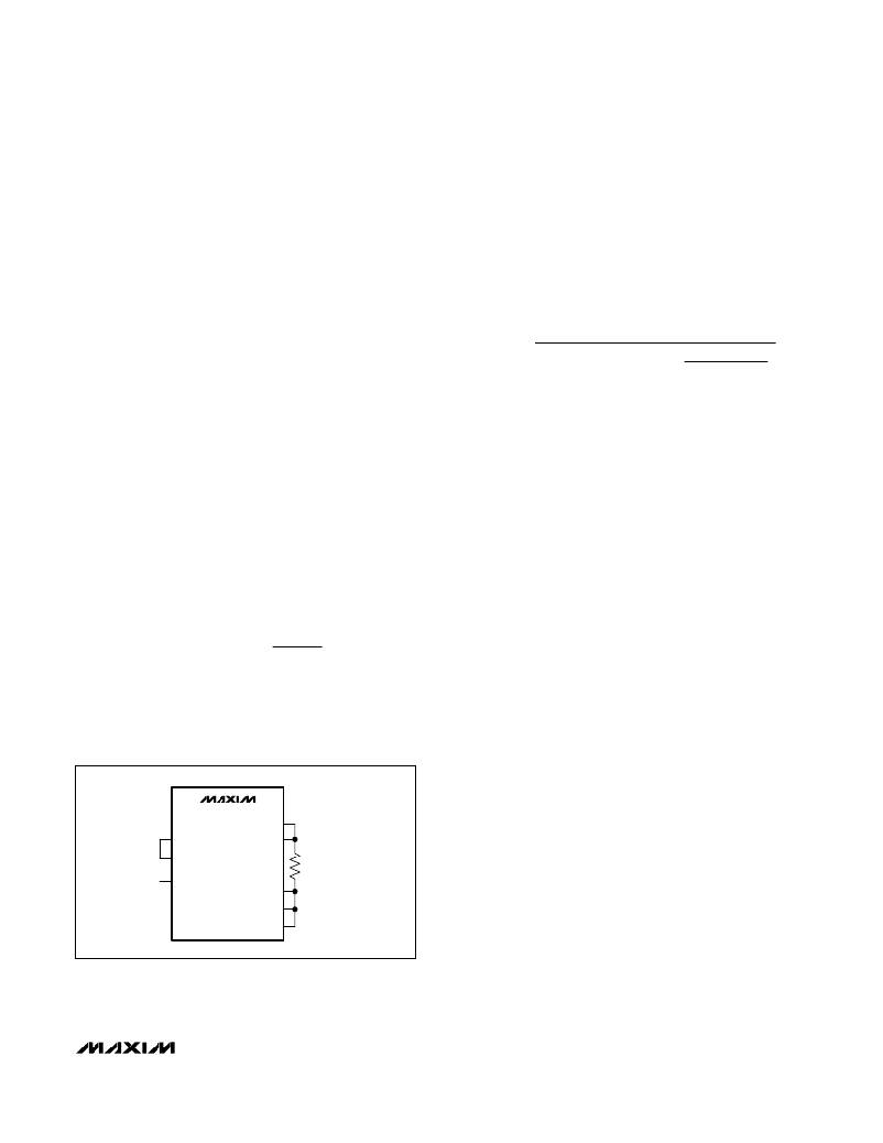
�MAX5042/MAX5043�
�SRC�
�where� C� PCB� =� 14pF,�
�V� REG5� =� 5V,�
�f� S� =� switching� frequency,�
�V� TH� =� RCOSC� peak� trip� level.�
�The� delay� programmed� by� the� resistor� at� DRVDEL� lim-�
�its� the� power� MOSFET’s� maximum� duty� cycle� to� less�
�than� 50� percent.�
�SYNC� allows� synchronization� of� the� MAX5042/MAX5043�
�to� an� external� clock.� For� proper� synchronization,� set� the�
�external� SYNC� frequency� 15%� to� 20%� higher� than� the�
�programmed� free-running� frequency� of� the� MAX5042/�
�MAX5043� ’s� internal� oscillator.� The� actual� switching�
�frequency� will� be� half� the� synchronizing� frequency.�
�Integrating� Fault� Protection�
�The� integrating� fault� protection� feature� allows� the�
�MAX5042/MAX5043� to� ignore� transient� overcurrent�
�conditions� for� a� programmable� amount� of� time,� giving�
�the� power� supply� time� to� behave� like� a� current� source�
�to� the� load.� This� can� happen,� for� example,� under� load-�
�current� transients� when� the� control� loop� requests� maxi-�
�mum� current� to� keep� the� output� voltage� from� going� out�
�of� regulation.� Program� the� ignore� time� externally� by�
�connecting� a� capacitor� to� FLTINT.� Under� sustained�
�overcurrent� faults,� the� voltage� across� this� capacitor�
�ramps� up� toward� the� FLTINT� shutdown� threshold� (typi-�
�cally� 2.7V).� When� FLTINT� reaches� the� threshold,� the�
�RAMP�
�CSOUT�
�OPTO�
�CSP�
�CSN�
�PWMPNEG�
�PWMNEG�
�RS�
�50m� ?�
�(APPROXIMATELY�
�35W� TO� 40W)�
�power� supply� shuts� down.� A� high-value� bleed� resistor�
�connected� in� parallel� with� the� FLTINT� capacitor� allows�
�the� capacitor� to� discharge� toward� the� restart� threshold�
�(typically� 1.8V).� Crossing� the� restart� threshold� soft-�
�starts� the� supply� again.�
�The� ILIM� comparator� provides� cycle-by-cycle� current�
�limiting� with� a� typical� threshold� of� 156mV.� The� fault� inte-�
�gration� circuit� works� by� forcing� an� 80μA� current� out� of�
�Figure� 6.� Simplified� Connection� Diagram� for� Current-Mode�
�Control�
�FLTINT� for� one� clock� cycle� every� time� the� current-limit�
�comparator� (Figures� 3� and� 4,� ILIM)� trips.� Use� the� fol-�
�lowing� formula� to� calculate� the� approximate� capaci-�
�tance� (C� FLTINT� )� needed� for� the� desired� shutdown� time.�
�______________________________________________________________________________________�
�17�
�相关PDF资料 |
PDF描述 |
|---|---|
| PX0441/2M00 | CABLE IP68 MINI B TO A USB 2M |
| BA6219BFP-YE2 | IC DRIVER MOTOR REVERSE HSOP25 |
| VI-J5Y-EZ-S | CONVERTER MOD DC/DC 3.3V 16.5W |
| VI-J5W-EZ-S | CONVERTER MOD DC/DC 5.5V 25W |
| PX0840/B/2M00 | CABLE PLUG IP68 USB B-A 2M |
相关代理商/技术参数 |
参数描述 |
|---|---|
| MAX5042ETN+ | 制造商:Maxim Integrated Products 功能描述:- Rail/Tube |
| MAX5042EVKIT | 功能描述:电源管理IC开发工具 MAX5042 Eval Kit RoHS:否 制造商:Maxim Integrated 产品:Evaluation Kits 类型:Battery Management 工具用于评估:MAX17710GB 输入电压: 输出电压:1.8 V |
| MAX5043ATN+ | 制造商:Maxim Integrated Products 功能描述:- Rail/Tube |
| MAX5043ETN | 功能描述:开关变换器、稳压器与控制器 Two-Switch Power IC w/Power MOSFET RoHS:否 制造商:Texas Instruments 输出电压:1.2 V to 10 V 输出电流:300 mA 输出功率: 输入电压:3 V to 17 V 开关频率:1 MHz 工作温度范围: 安装风格:SMD/SMT 封装 / 箱体:WSON-8 封装:Reel |
| MAX5043ETN+ | 功能描述:开关变换器、稳压器与控制器 Two-Switch Power IC w/Power MOSFET RoHS:否 制造商:Texas Instruments 输出电压:1.2 V to 10 V 输出电流:300 mA 输出功率: 输入电压:3 V to 17 V 开关频率:1 MHz 工作温度范围: 安装风格:SMD/SMT 封装 / 箱体:WSON-8 封装:Reel |
发布紧急采购,3分钟左右您将得到回复。