- 您现在的位置:买卖IC网 > PDF目录15858 > MAX6882ETE+ (Maxim Integrated Products)IC SEQUENCE/SUPERVISOR 16TQFN PDF资料下载
参数资料
| 型号: | MAX6882ETE+ |
| 厂商: | Maxim Integrated Products |
| 文件页数: | 14/19页 |
| 文件大小: | 0K |
| 描述: | IC SEQUENCE/SUPERVISOR 16TQFN |
| 产品培训模块: | Lead (SnPb) Finish for COTS Obsolescence Mitigation Program |
| 标准包装: | 75 |
| 类型: | 序列发生器 |
| 监视电压数目: | 2 |
| 输出: | 开路漏极或开路集电极 |
| 复位: | 低有效 |
| 复位超时: | 可调节/可选择 |
| 电压 - 阀值: | 可调节/可选择 |
| 工作温度: | -40°C ~ 85°C |
| 安装类型: | 表面贴装 |
| 封装/外壳: | 16-WQFN 裸露焊盘 |
| 供应商设备封装: | 16-TQFN-EP(4x4) |
| 包装: | 管件 |
�� �
�
�Dual-/Triple-Voltage,� Power-Supply�
�Sequencers/Supervisors�
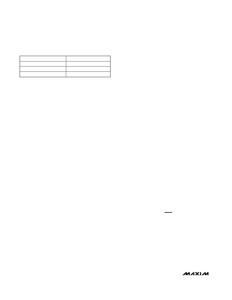
�Table� 1.� C� SLEW� Timing� Formulas�
�ABP� Input� (MAX6880/MAX6882)�
�ABP� powers� the� analog� circuitry.� Bypass� ABP� to� GND�
�TIME� PERIOD�
�Slew� Rate�
�t� RETRY�
�t� FAULT�
�FORMULAS�
�(9.35� x� 10� -8� )� /� C� SLEW�
�3.506� x� 10� 9� x� C� SLEW�
�2.191� x� 10� 8� x� C� SLEW�
�with� a� 1μF� ceramic� capacitor� installed� as� close� to� the�
�device� as� possible.� ABP� takes� the� highest� voltage� of�
�IN_.� Do� not� use� ABP� to� provide� power� to� external� cir-�
�cuitry.� ABP� maintains� the� device� supply� voltage� during�
�rapid� power-down� conditions.�
�Limiting� Inrush� Current�
�The� capacitor� (C� SLEW� )� at� SLEW� to� ground,� controls� the�
�OUT_� slew� rate,� thus� controlling� the� inrush� current�
�required� to� charge� the� load� capacitor� at� OUT_.� Using�
�the� programmed� slew� rate,� limit� the� inrush� current� by�
�using� the� following� formula:�
�I� INRUSH� =� C� OUT� x� SR�
�where� I� INRUSH� is� in� amperes,� C� OUT� is� in� farads,� and� SR�
�is� in� V/s.�
�Delay� Time� Input� (DELAY)�
�To� adjust� the� desired� delay� period� (t� DELAY� )� before�
�sequencing� is� enabled,� connect� a� capacitor� (C� DELAY� )�
�between� DELAY� to� ground� (see� Figures� 2� to� 5).� The�
�selected� delay� time� is� also� enforced� when� EN/� UV� rises�
�from� low� to� high� when� all� the� input� voltages� are� present.�
�Use� the� following� formula� to� calculate� the� delay� time:�
�t� DELAY� =� 200μs� +� (500k� ?� x� C� DELAY� )�
�where� t� DELAY� is� in� μs� and� C� DELAY� is� in� farads.� Leave�
�DELAY� unconnected� for� the� default� 200μs� delay.�
�Timeout� Period� Input� (TIMEOUT)�
�(MAX6880/MAX6882)�
�These� devices� feature� a� PG/� RST� timeout� period.�
�Connect� a� capacitor� (C� TIMEOUT� )� from� TIMEOUT� to�
�ground� to� program� the� PG/� RST� timeout� period.� After� all�
�OUT_� outputs� exceed� their� IN_� referenced� thresholds�
�(V� TH_PG� ),� PG/� RST� remains� low� for� the� selected� timeout�
�period� t� TIMEOUT� (see� Figure� 3).�
�t� TIMEOUT� =� 200μs� +� (500k� ?� x� C� TIMEOUT� )�
�where� t� TIMEOUT� is� in� μs� and� C� TIMEOUT� is� in� farads.�
�Leave� TIMEOUT� unconnected� for� the� default� 200μs�
�timeout� delay.�
�Logic-Enable� Input� (EN� /� U� V� )�
�Drive� logic� EN/� UV� input� above� V� EN_R� to� initiate� voltage�
�sequencing� during� power-up� operation.� Drive� logic�
�EN/� UV� below� V� EN_F� to� initiate� tracking� power-down�
�operation.� Connect� EN/� UV� to� an� external� resistor-�
�divider� network� to� set� the� external� undervoltage� lockout�
�threshold.�
�OUT1/OUT2/OUT3�
�The� MAX6880/MAX6881� monitor� three� OUT_� and� the�
�MAX6882/MAX6883� monitor� two� OUT_� outputs� to� con-�
�trol� the� sequencing� performance.� After� the� internal� sup-�
�ply� (ABP)� exceeds� the� minimum� voltage� (2.7V)�
�requirements,� EN/� UV� >� V� EN_R� ,� and� IN1/IN2/IN3� are� all�
�greater� than� their� adjusted� SET_� thresholds,� OUT1/�
�OUT2/OUT3� begin� to� sequence.�
�During� fault� conditions,� an� internal� pulldown� resistor�
�(100� ?� )� on� OUT_� is� enabled� to� help� discharge� load�
�capacitance� (100� ?� is� connected� for� fast� power-down�
�control).�
�Outputs�
�GATE_�
�The� MAX6880–MAX6883� feature� up� to� three� GATE_� out-�
�puts� to� drive� up� to� three� external� n-channel� FET� gates.�
�The� following� conditions� must� be� met� before� GATE_�
�begins� enhancing� the� external� n-channel� FET_:�
�1)� All� SET_� inputs� (SET1/SET2/SET3)� are� above� their�
�0.5V� thresholds.�
�2)� At� least� one� IN_� input� is� above� the� minimum� operat-�
�ing� voltage� (2.7V).�
�3)� EN/� UV� >� 1.25V.�
�At� power-up� mode,� GATE_� voltages� are� enhanced� by�
�control� loops� so� all� OUT_� voltages� sequence� at� a�
�capacitor-adjusted� slew� rate.� Each� GATE_� is� internally�
�pulled� up� to� 5V� above� its� relative� IN_� voltage� to� fully�
�enhance� the� external� n-channel� FET� when� power-up� is�
�complete.�
�Power-Good� Output� (PG/RST)� (MAX6880/MAX6882)�
�The� MAX6880/MAX6882� include� a� power-good� (PG/� RST� )�
�output.� PG/� RST� is� an� open-drain� output� and� requires� an�
�external� pullup� resistor.�
�All� the� OUT_� outputs� must� exceed� their� IN_� referenced�
�thresholds� (IN_� x� V� TH_PG� )� for� the� selected� reset� timeout�
�period� t� TIMEOUT� (see� the� TIMEOUT� Period� Input� sec-�
�tion)� before� PG/� RST� asserts� high.� PG/� RST� stays� low� for�
�the� selected� reset� timeout� period� (t� TIMEOUT� )� after� all�
�the� OUT_� voltages� exceed� their� IN_� referenced� thresh-�
�olds.� PG/� RST� goes� low� when� V� SET_� <� V� TH� or� V� EN/� UV� <�
�V� EN_R� (see� Figure� 2).�
�14�
�______________________________________________________________________________________�
�相关PDF资料 |
PDF描述 |
|---|---|
| CDRH8D43NP-220NC | INDUCTOR POWER 22UH 1.8A SMD |
| MAX6439UTAJYD3+T | IC BATTERY MON SNGL SOT23-6 |
| EBA22DRSN-S288 | CONN EDGECARD 44POS .125 EXTEND |
| MAX6439UTBITD3+T | IC BATTERY MON SNGL SOT23-6 |
| MAX6709FUB+ | IC VOLT MONITOR QUAD 10-UMAX |
相关代理商/技术参数 |
参数描述 |
|---|---|
| MAX6882ETE+ | 功能描述:监控电路 Dual Power-Sup Sequencer RoHS:否 制造商:STMicroelectronics 监测电压数: 监测电压: 欠电压阈值: 过电压阈值: 输出类型:Active Low, Open Drain 人工复位:Resettable 监视器:No Watchdog 电池备用开关:No Backup 上电复位延迟(典型值):10 s 电源电压-最大:5.5 V 最大工作温度:+ 85 C 安装风格:SMD/SMT 封装 / 箱体:UDFN-6 封装:Reel |
| MAX6882ETE+T | 功能描述:监控电路 Dual Power-Sup Sequencer RoHS:否 制造商:STMicroelectronics 监测电压数: 监测电压: 欠电压阈值: 过电压阈值: 输出类型:Active Low, Open Drain 人工复位:Resettable 监视器:No Watchdog 电池备用开关:No Backup 上电复位延迟(典型值):10 s 电源电压-最大:5.5 V 最大工作温度:+ 85 C 安装风格:SMD/SMT 封装 / 箱体:UDFN-6 封装:Reel |
| MAX6882ETE-T | 功能描述:监控电路 RoHS:否 制造商:STMicroelectronics 监测电压数: 监测电压: 欠电压阈值: 过电压阈值: 输出类型:Active Low, Open Drain 人工复位:Resettable 监视器:No Watchdog 电池备用开关:No Backup 上电复位延迟(典型值):10 s 电源电压-最大:5.5 V 最大工作温度:+ 85 C 安装风格:SMD/SMT 封装 / 箱体:UDFN-6 封装:Reel |
| MAX6883ETE | 功能描述:监控电路 RoHS:否 制造商:STMicroelectronics 监测电压数: 监测电压: 欠电压阈值: 过电压阈值: 输出类型:Active Low, Open Drain 人工复位:Resettable 监视器:No Watchdog 电池备用开关:No Backup 上电复位延迟(典型值):10 s 电源电压-最大:5.5 V 最大工作温度:+ 85 C 安装风格:SMD/SMT 封装 / 箱体:UDFN-6 封装:Reel |
| MAX6883ETE+ | 功能描述:监控电路 Dual Power-Sup Sequencer RoHS:否 制造商:STMicroelectronics 监测电压数: 监测电压: 欠电压阈值: 过电压阈值: 输出类型:Active Low, Open Drain 人工复位:Resettable 监视器:No Watchdog 电池备用开关:No Backup 上电复位延迟(典型值):10 s 电源电压-最大:5.5 V 最大工作温度:+ 85 C 安装风格:SMD/SMT 封装 / 箱体:UDFN-6 封装:Reel |
发布紧急采购,3分钟左右您将得到回复。