- 您现在的位置:买卖IC网 > PDF目录1946 > MAX9249GCM/V+ (Maxim Integrated Products)IC SERIALIZER GMSL LVDS 48TQFP PDF资料下载
参数资料
| 型号: | MAX9249GCM/V+ |
| 厂商: | Maxim Integrated Products |
| 文件页数: | 22/36页 |
| 文件大小: | 0K |
| 描述: | IC SERIALIZER GMSL LVDS 48TQFP |
| 产品培训模块: | Lead (SnPb) Finish for COTS Obsolescence Mitigation Program |
| 标准包装: | 250 |
| 功能: | 串行器 |
| 数据速率: | 2.5Gbs |
| 输入类型: | LVDS |
| 输出类型: | 串行 |
| 电源电压: | 3 V ~ 3.6 V |
| 工作温度: | -40°C ~ 105°C |
| 安装类型: | 表面贴装 |
| 封装/外壳: | 48-TQFN 裸露焊盘 |
| 供应商设备封装: | 48-TQFP(7x7) |
| 包装: | 管件 |
第1页第2页第3页第4页第5页第6页第7页第8页第9页第10页第11页第12页第13页第14页第15页第16页第17页第18页第19页第20页第21页当前第22页第23页第24页第25页第26页第27页第28页第29页第30页第31页第32页第33页第34页第35页第36页
______________________________________________________________________________________ 29
MAX9249
Gigabit Multimedia Serial Link
Serializer with LVDS System Interface
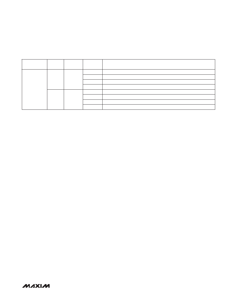
Table 10. Line-Fault Mapping
Choosing I2C/UART Pullup Resistors
Both I2C/UART open-drain lines require pullup resis-
tors to provide a logic-high level. There are trade-offs
between power dissipation and speed, and a compro-
mise made in choosing pullup resistor values. Every
device connected to the bus introduces some capaci-
tance even when the device is not in operation. I2C
specifies 300ns rise times to go from low to high (30% to
70%) for fast mode, which is defined for data rates up to
400kbps (see the I2C specifications in the AC Electrical
Characteristics section for details). To meet the fast-
mode rise-time requirement, choose the pullup resistors
so that rise time tR = 0.85 x RPULLUP x CBUS < 300ns.
The waveforms are not recognized if the transition time
becomes too slow. The MAX9249 supports I2C/UART
rates up to 1Mbps.
AC-Coupling
AC-coupling isolates the receiver from DC voltages up
to the voltage rating of the capacitor. Four capacitors—
two at the serializer output and two at the deserializer
input—are needed for proper link operation and to pro-
vide protection if either end of the cable is shorted to a
high voltage. AC-coupling blocks low-frequency ground
shifts and low-frequency common-mode noise.
Selection of AC-Coupling Capacitors
Voltage droop and the digital sum variation (DSV) of
transmitted symbols cause signal transitions to start
from different voltage levels. Because the transition time
is finite, starting the signal transition from different volt-
age levels causes timing jitter. The time constant for an
AC-coupled link needs to be chosen to reduce droop
and jitter to an acceptable level. The RC network for an
AC-coupled link consists of the CML receiver termination
resistor (RTR), the CML driver termination resistor (RTD),
and the series AC-coupling capacitors (C). The RC time
constant for four equal-value series capacitors is (C x
(RTD + RTR))/4. RTD and RTR are required to match the
transmission line impedance (usually 100I). This leaves
the capacitor selection to change the system time con-
stant. Use at least 0.2FF high-frequency surface-mount
ceramic capacitors, with sufficient voltage rating to with-
stand a short to battery, to pass the lower speed reverse
control-channel signal. Use capacitors with a case size
less than 3.2mm x 1.6mm to have lower parasitic effects
to the high-speed signal.
Power-Supply Circuits and Bypassing
The MAX9249 uses a VAVDD and VDVDD of 1.7V to
1.9V, and a VLVDSVDD of 3.0V to 3.6V. All single-ended
inputs and outputs on the MAX9249 derive power from a
VIOVDD of 1.7V to 3.6V, which scale with IOVDD. Proper
voltage-supply bypassing is essential for high-frequency
circuit stability.
Cables and Connectors
Interconnect for CML typically has a differential imped-
ance of 100I. Use cables and connectors that have
matched differential impedance to minimize impedance
discontinuities. Twisted-pair and shielded twisted-pair
cables tend to generate less EMI due to magnetic-field
canceling effects. Balanced cables pick up noise as
common mode rejected by the CML receiver. Table 11
lists the suggested cables and connectors used in the
GMSL link.
REGISTER
ADDRESS
BITS
NAME
VALUE
LINE-FAULT TYPE
0x08
D[3:2]
LFNEG
00
Negative cable wire shorted to battery
01
Negative cable wire shorted to ground
10
Normal operation
11
Negative cable wire open
D[1:0]
LFPOS
00
Positive cable wire shorted to battery
01
Positive cable wire shorted to ground
10
Normal operation
11
Positive cable wire open
相关PDF资料 |
PDF描述 |
|---|---|
| MAX9257AGTL/V+ | IC SERDE PROG UART/I2C 40TQFN |
| MAX9257GTL+T | IC SER/DESER PROG 40-TQFN |
| MAX9260GCB/V+ | IC DESERIALIZER GMSL 64TQFP |
| MAX9271GTJ/V+ | IC SERIALIZER 16BIT GMSL 32TQFN |
| MAX9272GTM/V+ | IC DSERIALIZER 28BIT GMSL 48TQFN |
相关代理商/技术参数 |
参数描述 |
|---|---|
| MAX924C/D | 功能描述:校验器 IC RoHS:否 制造商:STMicroelectronics 产品: 比较器类型: 通道数量: 输出类型:Push-Pull 电源电压-最大:5.5 V 电源电压-最小:1.1 V 补偿电压(最大值):6 mV 电源电流(最大值):1350 nA 响应时间: 最大工作温度:+ 125 C 安装风格:SMD/SMT 封装 / 箱体:SC-70-5 封装:Reel |
| MAX924CPE | 功能描述:校验器 IC RoHS:否 制造商:STMicroelectronics 产品: 比较器类型: 通道数量: 输出类型:Push-Pull 电源电压-最大:5.5 V 电源电压-最小:1.1 V 补偿电压(最大值):6 mV 电源电流(最大值):1350 nA 响应时间: 最大工作温度:+ 125 C 安装风格:SMD/SMT 封装 / 箱体:SC-70-5 封装:Reel |
| MAX924CPE+ | 功能描述:校验器 IC Quad Comparator w/1% Precision Ref RoHS:否 制造商:STMicroelectronics 产品: 比较器类型: 通道数量: 输出类型:Push-Pull 电源电压-最大:5.5 V 电源电压-最小:1.1 V 补偿电压(最大值):6 mV 电源电流(最大值):1350 nA 响应时间: 最大工作温度:+ 125 C 安装风格:SMD/SMT 封装 / 箱体:SC-70-5 封装:Reel |
| MAX924CSE | 功能描述:校验器 IC Quad Comparator w/1% Precision Ref RoHS:否 制造商:STMicroelectronics 产品: 比较器类型: 通道数量: 输出类型:Push-Pull 电源电压-最大:5.5 V 电源电压-最小:1.1 V 补偿电压(最大值):6 mV 电源电流(最大值):1350 nA 响应时间: 最大工作温度:+ 125 C 安装风格:SMD/SMT 封装 / 箱体:SC-70-5 封装:Reel |
| MAX924CSE+ | 功能描述:校验器 IC Quad Comparator w/1% Precision Ref RoHS:否 制造商:STMicroelectronics 产品: 比较器类型: 通道数量: 输出类型:Push-Pull 电源电压-最大:5.5 V 电源电压-最小:1.1 V 补偿电压(最大值):6 mV 电源电流(最大值):1350 nA 响应时间: 最大工作温度:+ 125 C 安装风格:SMD/SMT 封装 / 箱体:SC-70-5 封装:Reel |
发布紧急采购,3分钟左右您将得到回复。