- 您现在的位置:买卖IC网 > PDF目录11144 > MAX9670CTL+T (Maxim Integrated Products)IC AUDIO/VIDEO SWIT DUAL 40TQFN PDF资料下载
参数资料
| 型号: | MAX9670CTL+T |
| 厂商: | Maxim Integrated Products |
| 文件页数: | 10/44页 |
| 文件大小: | 0K |
| 描述: | IC AUDIO/VIDEO SWIT DUAL 40TQFN |
| 产品培训模块: | Lead (SnPb) Finish for COTS Obsolescence Mitigation Program |
| 标准包装: | 2,500 |
| 功能: | 音频/视频切换 |
| 电路: | 2 x SCART |
| 电压电源: | 单电源 |
| 电压 - 电源,单路/双路(±): | 3.3 V ~ 12 V |
| 工作温度: | 0°C ~ 70°C |
| 安装类型: | 表面贴装 |
| 封装/外壳: | 40-WFQFN 裸露焊盘 |
| 供应商设备封装: | 40-TQFN-EP(6x6) |
| 包装: | 带卷 (TR) |
| 配用: | MAX9670EVKIT+-ND - EVALUATION KIT FOR MAX9670 |
第1页第2页第3页第4页第5页第6页第7页第8页第9页当前第10页第11页第12页第13页第14页第15页第16页第17页第18页第19页第20页第21页第22页第23页第24页第25页第26页第27页第28页第29页第30页第31页第32页第33页第34页第35页第36页第37页第38页第39页第40页第41页第42页第43页第44页
MAX9670/MAX9671
Low-Power Audio/Video Switch with Audio
Volume Control for Dual SCART Connectors
18
______________________________________________________________________________________
video sources that are sent to the VCR SCART connec-
tor are controlled by bits 0 to 2 of the VCR Video Input
Control register (08h). See Tables 10, 14, and 16. The
video outputs can be enabled or disabled by bits 2
through 7 of the Output Enable register (0Dh). See
Table 18.
Slow Switching
The MAX9670/MAX9671 support the IEC 933-1,
Amendment 1, three-level slow switching that selects
the aspect ratio for the display (TV). Under I2C control,
the MAX9670/MAX9671 set the slow-switching output
voltage level. Table 2 shows the valid input levels of the
slow-switching signal and the corresponding operating
modes of the display device.
Two bidirectional ports are available for slow-switching
signals for the TV and VCR. The slow-switching input
status is continuously read and stored in the Status reg-
ister (0Eh). The slow-switching outputs can be set to a
logic level or high impedance by writing to the TV Video
Output Control register (07h) and the VCR Video Output
Control register (09h). When enabled, INT becomes
active low if the voltage level changes on TV_SS or
VCR_SS. See Tables 10, 15, 17, and 20.
Fast Switching
The fast-switching signal was originally used to switch
between CVBS and RGB signals on a pixel-by-pixel
basis so that on-screen display (OSD) information
could be inserted. Since modern set-top box decoder
chips have integrated OSD circuitry, there is no need to
create OSD information using the older technique. Now,
the fast-switching signal is just used to switch between
CVBS and RGB signal sources.
Set the source of the fast-switching signal by writing to
bits 4 and 3 of the TV Video Output Control register
(07h). The fast-switching signal to the TV SCART con-
nector can be enabled or disabled by bit 1 of the Output
Enable register (0Dh). See Tables 10, 15, and 18.
I2C Serial Interface
The MAX9670/MAX9671 feature an I2C/SMBus-com-
patible, 2-wire serial interface consisting of a serial-data
line (SDA) and a serial-clock line (SCL). SDA and SCL
facilitate communication between the MAX9670/
MAX9671 and the master at clock rates up to 400kHz.
Figure 6 shows the 2-wire interface timing diagram. The
master generates SCL and initiates data transfer on the
bus. A master device writes data to the MAX9670/
MAX9671 by transmitting a START (S) condition, the
proper slave address with the R/W bit set to 0, followed
by the register address and then the data word. Each
transmit sequence is framed by a START and a STOP
(P) condition. Each word transmitted to the
MAX9670/MAX9671 is 8 bits long and is followed by an
acknowledge clock pulse. A master reads from the
MAX9670/MAX9671 by transmitting the slave address
with the R/W bit set to 0, the register address of the reg-
ister to be read, a REPEATED START (Sr) condition, the
slave address with the R/W bit set to 1, followed by a
series of SCL pulses. The MAX9670/MAX9671 transmit
data on SDA in sync with the master-generated SCL
pulses. The master acknowledges receipt of each byte
of data. Each read sequence is framed by a START or
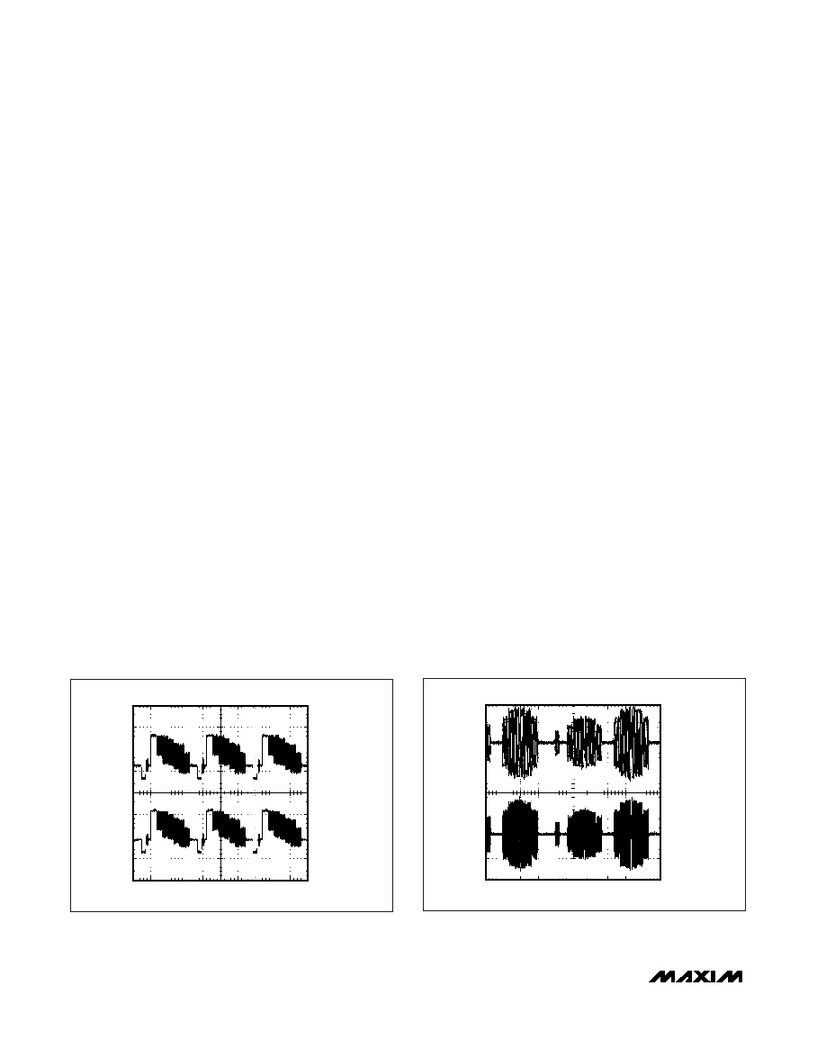
MAX9670 fig04
20
s/div
INPUT
500mV/div
OUTPUT
500mV/div
Figure 4. MAX9670/MAX9671 Video Output with CVBS Signal,
Multiburst Video Test Signal Shown
MAX9670 fig05
10
s/div
INPUT
200mV/div
OUTPUT
200mV/div
Figure 5. MAX9670/MAX9671 Video Output with Chroma (C)
Signal, Multiburst Video Test Signal Shown
相关PDF资料 |
PDF描述 |
|---|---|
| VE-B60-IX-F1 | CONVERTER MOD DC/DC 5V 75W |
| MAX4751EGE+T | IC SWITCH QUAD SPST 16QFN |
| VE-B60-IW-F4 | CONVERTER MOD DC/DC 5V 100W |
| VE-B60-IW-F3 | CONVERTER MOD DC/DC 5V 100W |
| VE-B60-IW-F1 | CONVERTER MOD DC/DC 5V 100W |
相关代理商/技术参数 |
参数描述 |
|---|---|
| MAX9670EVKIT+ | 功能描述:交换机 IC 开发工具 Low-Power A/V Switch w/Audio Volume Cntrl RoHS:否 制造商:Maxim Integrated 产品:Evaluation Kits 类型:USB Power Switches 工具用于评估:MAX4984E 工作电源电压:2.8 V to 5.5 V |
| MAX9671CTH+ | 功能描述:视频开关 IC Low-Power A/V Switch w/Audio Volume Cntrl RoHS:否 制造商:Texas Instruments 开关数量:4 开启电阻(最大值):12 Ohms 传播延迟时间: 开启时间(最大值): 关闭时间(最大值): 最大工作温度:+ 85 C 最小工作温度:- 40 C 封装 / 箱体:WQFN-42 封装:Reel |
| MAX9671CTH+T | 功能描述:视频开关 IC Low-Power A/V Switch w/Audio Volume Cntrl RoHS:否 制造商:Texas Instruments 开关数量:4 开启电阻(最大值):12 Ohms 传播延迟时间: 开启时间(最大值): 关闭时间(最大值): 最大工作温度:+ 85 C 最小工作温度:- 40 C 封装 / 箱体:WQFN-42 封装:Reel |
| MAX9671EVKIT+ | 功能描述:交换机 IC 开发工具 Low-Power A/V Switch w/Audio Volume Cntrl RoHS:否 制造商:Maxim Integrated 产品:Evaluation Kits 类型:USB Power Switches 工具用于评估:MAX4984E 工作电源电压:2.8 V to 5.5 V |
| MAX9672ETI+ | 功能描述:LCD Gamma缓冲器 10-Bit Prog Gamma Reference System RoHS:否 制造商:Maxim Integrated 输入补偿电压: 转换速度: 电源电压-最大:20 V 电源电压-最小:9 V 电源电流: 最大功率耗散: 最大工作温度:+ 85 C 安装风格:SMD/SMT 封装 / 箱体:TQFN-38 封装:Tube |
发布紧急采购,3分钟左右您将得到回复。