- 您现在的位置:买卖IC网 > PDF目录80361 > MAXQ610X-0000+ (MAXIM INTEGRATED PRODUCTS INC) 16-BIT, FLASH, 12 MHz, RISC MICROCONTROLLER, UUC PDF资料下载
参数资料
| 型号: | MAXQ610X-0000+ |
| 厂商: | MAXIM INTEGRATED PRODUCTS INC |
| 元件分类: | 微控制器/微处理器 |
| 英文描述: | 16-BIT, FLASH, 12 MHz, RISC MICROCONTROLLER, UUC |
| 封装: | DIE |
| 文件页数: | 5/29页 |
| 文件大小: | 827K |
| 代理商: | MAXQ610X-0000+ |
第1页第2页第3页第4页当前第5页第6页第7页第8页第9页第10页第11页第12页第13页第14页第15页第16页第17页第18页第19页第20页第21页第22页第23页第24页第25页第26页第27页第28页第29页
MAXQ610
16-Bit Microcontroller with Infrared Module
______________________________________________________________________________________
13
The watchdog timer functions as the source of both the
watchdog-timer timeout and the watchdog-timer reset.
The timeout period can be programmed in a range of
215 to 224 system clock cycles. An interrupt is generat-
ed when the timeout period expires if the interrupt is
enabled. All watchdog-timer resets follow the pro-
grammed interrupt timeouts by 512 system clock
cycles. If the watchdog timer is not restarted for another
full interval in this time period, a system reset occurs
when the reset timeout expires. See Table 2.
IR Carrier Generation and
Modulation Timer
The dedicated IR timer/counter module simplifies low-
speed IR communication. The IR timer implements two
pins (IRTX and IRRX) for supporting IR transmit and
receive, respectively. The IRTX pin has no correspond-
ing port pin designation, so the standard PD, PO, and
PI port control status bits are not present. However, the
IRTX pin output can be manipulated high or low using
the PWCN.IRTXOUT and PWCN.IRTXOE bits when the
IR timer is not enabled (i.e., IREN = 0).
The IR timer is composed of two separate timing enti-
ties: a carrier generator and a carrier modulator. The
carrier generation module uses the 16-bit IR Carrier
register (IRCA) to define the high and low time of the
carrier through the IR carrier high byte (IRCAH) and IR
carrier low byte (IRCAL). The carrier modulator uses the
IR data bit (IRDATA) and IR Modulator Time register
(IRMT) to determine whether the carrier or the idle con-
dition is present on IRTX.
The IR timer is enabled when the IR enable bit (IREN) is
set to 1. The IR Value register (IRV) defines the begin-
ning value for the carrier modulator. During transmis-
sion, the IRV register is initially loaded with the IRMT
value and begins down counting towards 0000h,
whereas in receive mode it counts upward from the ini-
tial IRV register value. During the receive operation, the
IRV register can be configured to reload with 0000h
when capture occurs on detection of selected edges or
can be allowed to continue free-running throughout the
receive operation. An overflow occurs when the IR timer
value rolls over from 0FFFFh to 0000h. The IR overflow
flag (IROV) is set to 1 and an interrupt is generated if
enabled (IRIE = 1).
Carrier Generation Module
The IRCAH byte defines the carrier high time in terms of
the number of IR input clocks, whereas the IRCAL byte
defines the carrier low time.
IR Input Clock (fIRCLK) = fSYS/2IRDIV[1:0]
Carrier Frequency (fCARRIER) =
fIRCLK/(IRCAH + IRCAL + 2)
Carrier High Time = IRCAH + 1
Carrier Low Time = IRCAL + 1
Carrier Duty Cycle = (IRCAH + 1)/(IRCAH + IRCAL + 2)
During transmission, the IRCA register is latched for
each IRV downcount interval and is sampled along with
the IRTXPOL and IRDATA bits at the beginning of each
new IRV downcount interval so that duty-cycle variation
and frequency shifting is possible from one interval to
the next, which is illustrated in Figure 1.
Figure 2 illustrates the basic carrier generation and its
path to the IRTX output pin. The IR transmit polarity bit
(IRTXPOL) defines the starting/idle state and the carrier
polarity of the IRTX pin when the IR timer is enabled.
IR Transmission
During IR transmission (IRMODE = 1), the carrier gener-
ator creates the appropriate carrier waveform, while the
carrier modulator performs the modulation. The carrier
modulation can be performed as a function of carrier
cycles or IRCLK cycles dependent on the setting of the
IRCFME bit. When IRCFME = 0, the IRV downcounter is
clocked by the carrier frequency and thus the modula-
tion is a function of carrier cycles. When IRCFME = 1,
the IRV downcounter is clocked by IRCLK, allowing car-
rier modulation timing with IRCLK resolution.
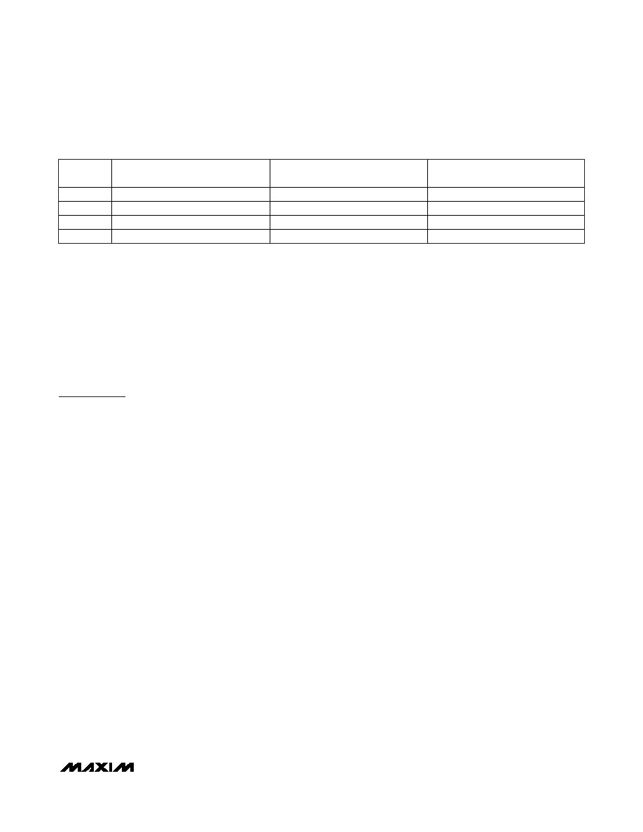
WD[1:0]
WATCHDOG CLOCK
WATCHDOG INTERRUPT TIMEOUT
WATCHDOG RESET AFTER
WATCHDOG INTERRUPT (μs)
00
Sysclk/215
2.7ms
42.7
01
Sysclk/218
21.9ms
42.7
10
Sysclk/221
174.7ms
42.7
11
Sysclk/224
1.4s
42.7
Table 2. Watchdog Interrupt Timeout (Sysclk = 12MHz, CD[1:0] = 00)
相关PDF资料 |
PDF描述 |
|---|---|
| MB89P568-101PMC1 | 8-BIT, MROM, 12.5 MHz, MICROCONTROLLER, PQFP80 |
| MB95F106AMWPFV | 8-BIT, FLASH, 16.25 MHz, MICROCONTROLLER, PQFP64 |
| M38024M6-XXXSP | 8-BIT, MROM, 8 MHz, MICROCONTROLLER, PDIP64 |
| M38067ECFP | 8-BIT, OTPROM, 8 MHz, MICROCONTROLLER, PQFP80 |
| MB90348EPMC | 16-BIT, MROM, 24 MHz, MICROCONTROLLER, PQFP100 |
相关代理商/技术参数 |
参数描述 |
|---|---|
| MAXQ610X-0000+ | 功能描述:MCU 16BIT W/IR MODULE BARE DIE RoHS:是 类别:集成电路 (IC) >> 嵌入式 - 微控制器, 系列:MAXQ® 产品培训模块:Lead (SnPb) Finish for COTS Obsolescence Mitigation Program 标准包装:260 系列:73S12xx 核心处理器:80515 芯体尺寸:8-位 速度:24MHz 连通性:I²C,智能卡,UART/USART,USB 外围设备:LED,POR,WDT 输入/输出数:9 程序存储器容量:64KB(64K x 8) 程序存储器类型:闪存 EEPROM 大小:- RAM 容量:2K x 8 电压 - 电源 (Vcc/Vdd):2.7 V ~ 5.5 V 数据转换器:- 振荡器型:内部 工作温度:-40°C ~ 85°C 封装/外壳:68-VFQFN 裸露焊盘 包装:管件 |
| MAXQ610X-0001+ | 功能描述:MAXQ610X PROG TESTED DIE WAFFLE RoHS:是 类别:集成电路 (IC) >> 嵌入式 - 微控制器, 系列:MAXQ® 产品培训模块:Lead (SnPb) Finish for COTS Obsolescence Mitigation Program 标准包装:260 系列:73S12xx 核心处理器:80515 芯体尺寸:8-位 速度:24MHz 连通性:I²C,智能卡,UART/USART,USB 外围设备:LED,POR,WDT 输入/输出数:9 程序存储器容量:64KB(64K x 8) 程序存储器类型:闪存 EEPROM 大小:- RAM 容量:2K x 8 电压 - 电源 (Vcc/Vdd):2.7 V ~ 5.5 V 数据转换器:- 振荡器型:内部 工作温度:-40°C ~ 85°C 封装/外壳:68-VFQFN 裸露焊盘 包装:管件 |
| MAXQ610X-2001+ | 功能描述:16位微控制器 - MCU RoHS:否 制造商:Texas Instruments 核心:RISC 处理器系列:MSP430FR572x 数据总线宽度:16 bit 最大时钟频率:24 MHz 程序存储器大小:8 KB 数据 RAM 大小:1 KB 片上 ADC:Yes 工作电源电压:2 V to 3.6 V 工作温度范围:- 40 C to + 85 C 封装 / 箱体:VQFN-40 安装风格:SMD/SMT |
| MAXQ610X-2021+ | 制造商:Maxim Integrated Products 功能描述:16-BIT MICROCONTROLLER WITH INFRARED MODULE - Gel-pak, waffle pack, wafer, diced wafer on film |
| MAXQ610X-UEI+ | 制造商:Maxim Integrated Products 功能描述:MAXQ610 BLANK WLP UEI - Gel-pak, waffle pack, wafer, diced wafer on film |
发布紧急采购,3分钟左右您将得到回复。