- 您现在的位置:买卖IC网 > PDF目录69024 > MC12430FA (INTEGRATED DEVICE TECHNOLOGY INC) 800 MHz, OTHER CLOCK GENERATOR, PQFP32 PDF资料下载
参数资料
| 型号: | MC12430FA |
| 厂商: | INTEGRATED DEVICE TECHNOLOGY INC |
| 元件分类: | 时钟产生/分配 |
| 英文描述: | 800 MHz, OTHER CLOCK GENERATOR, PQFP32 |
| 封装: | PLASTIC, LQFP-32 |
| 文件页数: | 12/12页 |
| 文件大小: | 503K |
| 代理商: | MC12430FA |
MC12430
9
MOTOROLA
power and grounds and fully differential PLL), there still may
be applications in which overall performance is being
degraded due to system power supply noise. The power
supply filter and bypass schemes discussed in this section
should be adequate to eliminate power supply noise related
problems in most designs.
Jitter Performance of the MC12430
The MC12430 exhibits long term and cycle–to–cycle jitter
which rivals that of SAW based oscillators. This jitter
performance comes with the added flexibility one gets with a
synthesizer over a fixed frequency oscillator.
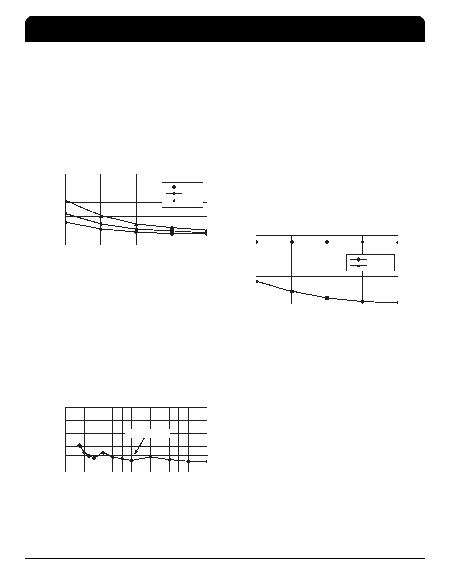
Figure 8. RMS PLL Jitter versus VCO Frequency
0
5
10
15
20
25
400
500
600
700
800
N=2
N=4
N=8
VCO Frequency (MHz)
RMS
Jitter
(ps)
Figure 8 illustrates the RMS jitter performance of the
MC12430 across its specified VCO frequency range. Note that
the jitter is a function of both the output frequency as well as
the VCO frequency, however the VCO frequency shows a
much stronger dependence. The data presented has not been
compensated for trigger jitter, this fact provides a measure of
guardband to the reported data.
The typical method of measuring the jitter is to accumulate
a large number of cycles, create a histogram of the edge
placements and record peak–to–peak as well as standard
deviations of the jitter. Care must be taken that the measured
edge is the edge immediately following the trigger edge. The
oscilloscope cannot collect adjacent pulses, rather it collects
pulses from a very large sample of pulses.
Figure 9. RMS Jitter versus Output Frequency
0
5
10
15
20
25
25 50 75 100 125 150 175 200 225 250 275 300 325 350 375 400
Output Frequency (MHz)
RMS
Jitter
(ps)
6.25ps Reference
Figure 9 shows the jitter as a function of the output
frequency. For the 12430, this information is probably of more
importance. The flat line represents an RMS jitter value that
corresponds to an 8 sigma
±25 ps peak–to–peak long term
period jitter. The graph shows that for output frequencies from
87.5 to 400 MHz the jitter falls within the
±25 ps peak–to–peak
specification. The general trend is that as the output frequency
is decreased the output edge jitter will increase.
The jitter data from Figure 8 and Figure 9 do not include the
performance of the 12430 when the output is in the divide by 1
mode. In divide by one mode, the MC12430 output jitter
distribution is bimodal. Since a bimodal distribution cannot be
accurately represented with an rms value, peak–to–peak
values of jitter for the divide by one mode are presented.
Figure 10 shows the peak–to–peak jitter of the 12430
output in divide by one mode as a function of output frequency.
Notice that as with the other modes the jitter improves with
increasing frequency. The
±65 ps shown in the data sheet
table represents a conservative value of jitter, especially for
the higher VCO, and thus output frequencies.
Figure 10. Peak–to–Peak Jitter versus
Output Frequency
40
60
80
100
120
140
400
500
600
700
800
Spec Limit
N=1
Output Frequency (MHz)
Peak-to-Peak
Jitter
(ps)
The jitter data presented should provide users with enough
information to determine the effect on their overall timing
budget. The jitter performance meets the needs of most
system designs while adding the flexibility of frequency
margining and field upgrades. These features are not
available with a fixed frequency SAW oscillator.
Output Voltage Swing vs Frequency
In the divide by one mode, the output rise and fall times will
limit the peak to peak output voltage swing. For a 400 MHz
output, the peak to peak swing of the 12430 output will be
approximately 700 mV. This swing will gradually degrade as
the output frequency increases, at 800 MHz the output swing
will be reduced to approximately 500 mV. For a worst case
analysis, it would be safe to assume that the 12430 output will
always generate at least a 500mV output swing. Note that
most high speed ECL receivers require only a few hundred
millivolt input swings for reliable operation. As a result, the
output generated by the 12430 will, under all conditions, be
sufficient for clocking standard ECL devices. Note that if a
larger swing is required the MC12430 could drive a clock
fanout buffer like the MC100EP111.
F
re
e
sc
a
le
S
e
m
ic
o
n
d
u
c
to
r,
I
Freescale Semiconductor, Inc.
For More Information On This Product,
Go to: www.freescale.com
n
c
..
.
MC12430
High Frequency Clock Synthesizer
NETCOM
IDT High Frequency Clock Synthesizer
Freescale Timing Solutions Organization has been acquired by Integrated Device Technology, Inc
MC12430
9
相关PDF资料 |
PDF描述 |
|---|---|
| MC13214R2 | SPECIALTY MICROPROCESSOR CIRCUIT, BGA71 |
| MC13224VR2 | SPECIALTY MICROPROCESSOR CIRCUIT, PBGA99 |
| MC13226V | SPECIALTY MICROPROCESSOR CIRCUIT, PBGA99 |
| MC13226VR2 | SPECIALTY MICROPROCESSOR CIRCUIT, PBGA99 |
| MC13224V | SPECIALTY MICROPROCESSOR CIRCUIT, PBGA99 |
相关代理商/技术参数 |
参数描述 |
|---|---|
| MC12430FN | 制造商:MOTOROLA 制造商全称:Motorola, Inc 功能描述:HIGH FREQUENCY PLL CLOCK GENERATOR |
| MC12439 | 制造商:MOTOROLA 制造商全称:Motorola, Inc 功能描述:HIGH FREQUENCY PLL CLOCK GENERATOR |
| MC12439FN | 制造商:Motorola Inc 功能描述: 制造商:Motorola Inc 功能描述:MISCELLANEOUS CLOCK GENERATOR, 28 Pin, Plastic, PLCC |
| MC1243F | 制造商:Rochester Electronics LLC 功能描述:- Bulk |
| MC1245L | 制造商:Rochester Electronics LLC 功能描述:- Bulk |
发布紧急采购,3分钟左右您将得到回复。