- 您现在的位置:买卖IC网 > PDF目录371008 > MC1311 (Motorola, Inc.) UNIVERSAL NARROWBAND FM RECEIVER INTEGRATED CIRCUIT PDF资料下载
参数资料
| 型号: | MC1311 |
| 厂商: | Motorola, Inc. |
| 英文描述: | UNIVERSAL NARROWBAND FM RECEIVER INTEGRATED CIRCUIT |
| 中文描述: | 通用窄带调频接收器集成电路 |
| 文件页数: | 26/68页 |
| 文件大小: | 1316K |
| 代理商: | MC1311 |
第1页第2页第3页第4页第5页第6页第7页第8页第9页第10页第11页第12页第13页第14页第15页第16页第17页第18页第19页第20页第21页第22页第23页第24页第25页当前第26页第27页第28页第29页第30页第31页第32页第33页第34页第35页第36页第37页第38页第39页第40页第41页第42页第43页第44页第45页第46页第47页第48页第49页第50页第51页第52页第53页第54页第55页第56页第57页第58页第59页第60页第61页第62页第63页第64页第65页第66页第67页第68页
MC13110A/B MC13111A/B
26
MOTOROLA ANALOG IC DEVICE DATA
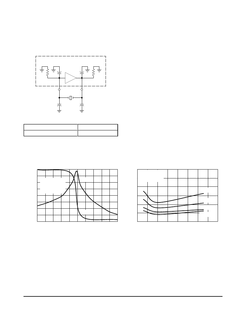
Second Local Oscillator
The 2nd LO is a CMOS oscillator. It is used as the PLL
reference oscillator and local oscillator for the second
frequency conversion in the RF receiver. It is designed to
utilize an external parallel resonant crystal. See schematic in
Figure 39.
Figure 39. Second Local Oscillator Schematic
2nd LO
RPI
CPI
RPO
CPO
Gm
LO2 In
LO2 Out
Xtal
C2
C1
ááááááááááááááááá
á
ááááááááááááááááá
áááááááááááááááá
ááááááááááááááá
á
áááááááááááááááá
Figure 41 shows a typical gain/phase response of the
second local oscillator. Load capacitance (CL), equivalent
series resistance (ESR), and even supply voltage will have
and affect on the 2nd LO response as shown in Figures 45
and 46. Except for the standby mode open loop gain is fairly
constant as supply voltage increases from 2.5 V. This is due
to the regulated voltage of 2.5 V on PLL Vref. From the graphs
it can seen that optimum performance is achieved when C1
equals C2 (C1/C2 = 1).
Figure 46 represents the ESR versus crystal load
capacitance for the 2nd LO. This relationship was defined by
using a 6.0 dB minimum loop gain margin at 3.6 V. This is
considered the minimum gain margin to guarantee oscillator
start–up.
Oscillator start–up is also significantly affected by the
crystal load capacitance selection. In Figures 42 and 43 the
relationship between crystal load capacitance, supply
voltage, and external load capacitance ratio (C2/C1), can be
seen. The lower the load capacitance the better the
performance.
Given the desired crystal load capacitance, C1 and C2
can be determined from Figure 47. It is also interesting to
point out that current consumption increases when C1
≠
C2,
as shown in Figure 44.
Be careful not to overdrive the crystal. This could cause a
noise problem. An external series resistor on the crystal
output can be added to reduce the drive level, if necessary.
Vg
0
6.0
10.235
15
S
CAPACITOR RATIO (C2:C1)
Figure 41. Second LO Gain/Phase @ –10 dBm
f, FREQUENCY (MHz)
Figure 42. Start–Up Time versus Capacitor
Ratio, Inactive to Rx Mode
10.24 MHz Crystal
CL = 10 pF
RS = 20
Gain
VCC = 5.0 V
VCC = 3.6 V
VCC = 2.3 V
VCC = 2.7 V
10
5.0
0
–5.0
–10
–15
–20
–25
5.0
4.0
3.0
2.0
1.0
0
10.24
10.245
Phase
90
67.5
45
22.5
0
–22.5
–45
–67.5
–90
0.5
1.0
1.5
2.0
2.5
3.0
3.5
4.0
10.24 MHz Crystal
CL = 10 pF
RS = 20
C1 = C2 = 15 pF
SECOND LOCAL OSCILLATOR
相关PDF资料 |
PDF描述 |
|---|---|
| MC13110AFB | UNIVERSAL NARROWBAND FM RECEIVER INTEGRATED CIRCUIT |
| MC13110AFTA | UNIVERSAL NARROWBAND FM RECEIVER INTEGRATED CIRCUIT |
| MC13110BFB | UNIVERSAL NARROWBAND FM RECEIVER INTEGRATED CIRCUIT |
| MC13111AFB | UNIVERSAL NARROWBAND FM RECEIVER INTEGRATED CIRCUIT |
| MC13110BFTA | UNIVERSAL NARROWBAND FM RECEIVER INTEGRATED CIRCUIT |
相关代理商/技术参数 |
参数描述 |
|---|---|
| MC13110 | 制造商:MOTOROLA 制造商全称:Motorola, Inc 功能描述:UNIVERSAL NARROWBAND FM RECEIVER INTEGRATED CIRCUIT |
| MC13110A | 制造商:MOTOROLA 制造商全称:Motorola, Inc 功能描述:UNIVERSAL CORDLESS TELEPHONE SUBSYSTEM IC |
| MC13110AFB | 制造商:MOTOROLA 制造商全称:Motorola, Inc 功能描述:UNIVERSAL CORDLESS TELEPHONE SUBSYSTEM IC |
| MC13110AFTA | 制造商:MOTOROLA 制造商全称:Motorola, Inc 功能描述:UNIVERSAL NARROWBAND FM RECEIVER INTEGRATED CIRCUIT |
| MC13110BFB | 制造商:MOTOROLA 制造商全称:Motorola, Inc 功能描述:UNIVERSAL NARROWBAND FM RECEIVER INTEGRATED CIRCUIT |
发布紧急采购,3分钟左右您将得到回复。