- 您现在的位置:买卖IC网 > PDF目录371008 > MC1311 (Motorola, Inc.) UNIVERSAL NARROWBAND FM RECEIVER INTEGRATED CIRCUIT PDF资料下载
参数资料
| 型号: | MC1311 |
| 厂商: | Motorola, Inc. |
| 英文描述: | UNIVERSAL NARROWBAND FM RECEIVER INTEGRATED CIRCUIT |
| 中文描述: | 通用窄带调频接收器集成电路 |
| 文件页数: | 28/68页 |
| 文件大小: | 1316K |
| 代理商: | MC1311 |
第1页第2页第3页第4页第5页第6页第7页第8页第9页第10页第11页第12页第13页第14页第15页第16页第17页第18页第19页第20页第21页第22页第23页第24页第25页第26页第27页当前第28页第29页第30页第31页第32页第33页第34页第35页第36页第37页第38页第39页第40页第41页第42页第43页第44页第45页第46页第47页第48页第49页第50页第51页第52页第53页第54页第55页第56页第57页第58页第59页第60页第61页第62页第63页第64页第65页第66页第67页第68页
MC13110A/B MC13111A/B
28
MOTOROLA ANALOG IC DEVICE DATA
IF Limiter and Demodulator
The limiting IF amplifier typically has about 110 dB of gain;
the frequency response starts rolling off at 1.0 MHz.
Decoupling capacitors should be placed close to Pins 31 and
32 to ensure low noise and stable operation. The IF input
impedance is 1.5 k
. This is a suitable match to 455 kHz
ceramic filters.
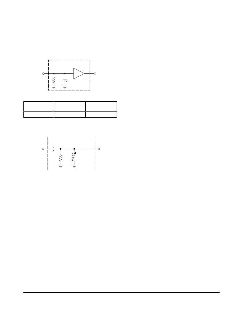
Figure 48. IF Limiter Schematic
Lim Out
Lim In
Limiter Stage
RPI
CPI
ááááááááááááááááá
á
ááááá
ááááááááááááááá
á
Figure 49. Limiter Input Impedance
ááááááááááááááá
ááááá
Input Impedance
á
Input Impedance
ááááááááááááááá
Figure 50. Quadrature Detector
Demodulator Schematic
Q Coil
Lim Out1
C28
10 p
Rext
22.1 k
Toko Q Coil
7MCS–8128Z
The quadrature detector is coupled to the IF with an
external capacitor between Pins 27 and 28. Thus, the
recovered signal level output is increased for a given
bandwidth by increasing the capacitor. The external
quadrature component may be either a LCR resonant circuit,
which may be adjustable, or a ceramic resonator which is
usually fixed tuned. (More on ceramic resonators later.)
The bandwidth performance of the detector is controlled
by the loaded Q of the LC tank circuit (Figure 50). The
following equation defines the components which set the
detector circuit’s bandwidth:
(1) RT = Q XL,
where RT is the equivalent shunt resistance across the LC
tank. XL is the reactance of the quadrature inductor at the IF
frequency (XL= 2
π
f L).
The 455 kHz IF center frequency is calculated by:
(2) fc = [2
π
(L Cp)1/2] – 1
where L is the parallel tank inductor. Cp is the equivalent
parallel capacitance of the parallel resonant tank circuit.
The following is a design example for a detector at 455
kHz and a specific loaded Q:
The loaded Q of the quadrature detector is chosen
somewhat less than the Q of the IF bandpass for margin. For
an IF frequency of 455 kHz and an IF bandpass of 20 kHz,
the IF bandpass Q is approximately 23; the loaded Q of the
quadrature tank is chosen slightly lower at 15.
Example:
Let the total external C = 180 pF. (Note: the capacitance is
the typical capacitance for the quad coil.) Since the external
capacitance is much greater than the internal device and
PCB parasitic capacitance, the parasitic capacitance may be
neglected.
Rewrite equation (2) and solve for L:
L = (0.159)2/(C fc2 )
L = 678
μ
H ; Thus, a standard value is chosen:
L = 680
μ
H (surface mount inductor)
The value of the total damping resistor to obtain the
required loaded Q of 15 can be calculated from equation (1):
RT = Q(2
π
f L)
RT = 15(2
π
)(0.455)(680) = 29.5 k
The internal resistance, Rint at the quadrature tank Pin 27
is approximately 100 k
and is considered in determining the
external resistance, Rext which is calculated from:
Rext = ((RT)(Rint))/(Rint – RT)
Rext = 41.8 k
;Thus, choose a standard value:
Rext = 39 k
In Figure 50, the Rext is chosen to be 22.1 k
. An
adjustable quadrature coil is selected. This tank circuit
represents one popular network used to match to the
455 kHz carrier frequency. The output of the detector is
represented as a “S–curve” as shown in Figure 52. The goal
is to tune the inductor in the area that is most linear on the
“S–curve” (minimum distortion) to optimize the performance
in terms of dc output level. The slope of the curve can also be
adjusted by choosing higher or lower values of Rext . This will
have an affect on the audio output level and bandwidth. As
Rext is increased the detector output slope will decrease.
The maximum audio output swing and distortion will be
reduced and the bandwidth increased. Of course, just the
opposite is true for smaller Rext.
A ceramic discriminator is recommended for the
quadrature circuit in applications where fixed tuning is
desired. The ceramic discriminator and a 5.6 k
resistor are
placed from Pin 27 to VCC . A 22 pF capacitor is placed from
Pin 28 to 27 to properly drive the discriminator. MuRata Erie
has designed a resonator for this part (CDBM455C48 for
USA & A/P regions and CDBM450C48 for Europe). This
resonator has been designed specifically for the
MC13110/111 family. Figure 51 shows the schematic used to
generate the “S–curve” and waveform shown in Figure 54
and 55.
相关PDF资料 |
PDF描述 |
|---|---|
| MC13110AFB | UNIVERSAL NARROWBAND FM RECEIVER INTEGRATED CIRCUIT |
| MC13110AFTA | UNIVERSAL NARROWBAND FM RECEIVER INTEGRATED CIRCUIT |
| MC13110BFB | UNIVERSAL NARROWBAND FM RECEIVER INTEGRATED CIRCUIT |
| MC13111AFB | UNIVERSAL NARROWBAND FM RECEIVER INTEGRATED CIRCUIT |
| MC13110BFTA | UNIVERSAL NARROWBAND FM RECEIVER INTEGRATED CIRCUIT |
相关代理商/技术参数 |
参数描述 |
|---|---|
| MC13110 | 制造商:MOTOROLA 制造商全称:Motorola, Inc 功能描述:UNIVERSAL NARROWBAND FM RECEIVER INTEGRATED CIRCUIT |
| MC13110A | 制造商:MOTOROLA 制造商全称:Motorola, Inc 功能描述:UNIVERSAL CORDLESS TELEPHONE SUBSYSTEM IC |
| MC13110AFB | 制造商:MOTOROLA 制造商全称:Motorola, Inc 功能描述:UNIVERSAL CORDLESS TELEPHONE SUBSYSTEM IC |
| MC13110AFTA | 制造商:MOTOROLA 制造商全称:Motorola, Inc 功能描述:UNIVERSAL NARROWBAND FM RECEIVER INTEGRATED CIRCUIT |
| MC13110BFB | 制造商:MOTOROLA 制造商全称:Motorola, Inc 功能描述:UNIVERSAL NARROWBAND FM RECEIVER INTEGRATED CIRCUIT |
发布紧急采购,3分钟左右您将得到回复。