- 您现在的位置:买卖IC网 > PDF目录11546 > MC33389CDW (Freescale Semiconductor)IC SYSTEM BASE W/CAN 28-SOIC PDF资料下载
参数资料
| 型号: | MC33389CDW |
| 厂商: | Freescale Semiconductor |
| 文件页数: | 19/49页 |
| 文件大小: | 0K |
| 描述: | IC SYSTEM BASE W/CAN 28-SOIC |
| 标准包装: | 26 |
| 控制器类型: | 系统基础芯片 |
| 接口: | CAN |
| 电源电压: | 5.5 V ~ 18 V |
| 电流 - 电源: | 45mA |
| 工作温度: | -40°C ~ 125°C |
| 安装类型: | 表面贴装 |
| 封装/外壳: | 28-SOIC(0.295",7.50mm 宽) |
| 供应商设备封装: | 28-SOIC W |
| 包装: | 管件 |
第1页第2页第3页第4页第5页第6页第7页第8页第9页第10页第11页第12页第13页第14页第15页第16页第17页第18页当前第19页第20页第21页第22页第23页第24页第25页第26页第27页第28页第29页第30页第31页第32页第33页第34页第35页第36页第37页第38页第39页第40页第41页第42页第43页第44页第45页第46页第47页第48页第49页
Analog Integrated Circuit Device Data
26
Freescale Semiconductor
33389
FUNCTIONAL DEVICE OPERATION
OPERATIONAL MODES
Local Wake-Up Consequences
In Normal or Stand-by modes, the real time state of each
wake-up input pin is stored in the readable Wake-Up Input
Control Register (WUIRTI). Wake-ups are detected
according to the selected option. A flag is set in the WUISR.
A maskable interrupt is then sent via INT output.
In the Sleep mode, a local wake-up leads to a jump to
Normal Request mode (via proper reset of the
microcontroller). A flag is set in the WUISR.
Wake-Up By SPI
In some applications, the microcontroller might be
supplied by an external VDD, remaining powered in SBC
Sleep mode. In this case, a feature is provided making
possible to wake-up the SBC by SPI activity.
After V1 is totally switched OFF in the Sleep mode (V1<
1.5 V), if a falling edge occurs on CS (crossing 2.5 V
threshold), a wake-up by SPI is detected, the SBC switches
to the Normal Request mode. A flag is set in ISR2.
Interrupt Output
The INT output may be activated in the following cases:
VBAT overvoltage (BatHigh)
VBAT undervoltage (BatFail)
High temperature on V1 or V2
Pre-warning temperature on V1 or V2
CAN bus failure
SPI error
Local wake-up (can be used for low battery detection)
Bus wake-up
All these interrupts are maskable. Please see the SPI
Reset Input/Output
The Reset (RST) pin is an input/output pin. The typical
reset duration from SBC to microcontroller is 1 ms. If
extended times are required, an external capacitor can be
used. SBC provides two RST output pull-up currents.
A typical 30
A pull up when Vreset is below 2.5 V and a
300 A pull up when reset voltage is higher than 2.5 V.
RST is also an input for the SBC. It means the 33389 is
forced to the Normal Request mode after RST is released by
the microcontroller.
GROUND SHIFT DETECTION
When normally working in a two-wire operating mode, the
CAN transmission can afford some ground shift between
different nodes without trouble. Nevertheless, in case of bus
failure, the transceiver switches to single-wire operation,
therefore working with less noise margin. The affordable
ground shift is decreased in this case.
The SBC is provided with a ground shift detection for
diagnosis purpose. Four ground shift levels (GSL) are
selectable and the detection is stored in the GSL register,
accessible via the SPI.
Detection Principle
The ground shift to detect is selected via the SPI from four
different values (-0.7 V, -1.2 V, -1.7 V, -2.2 V). The CANH
voltage is sensed at each TX falling edge (end of recessive
state). If it is detected to be below the selected ground shift
threshold, the bit SHIFT is set at one in the GSL register. No
filter is implemented. Required filtering for reliable detection
should be achieved by software (e.g. several trials).
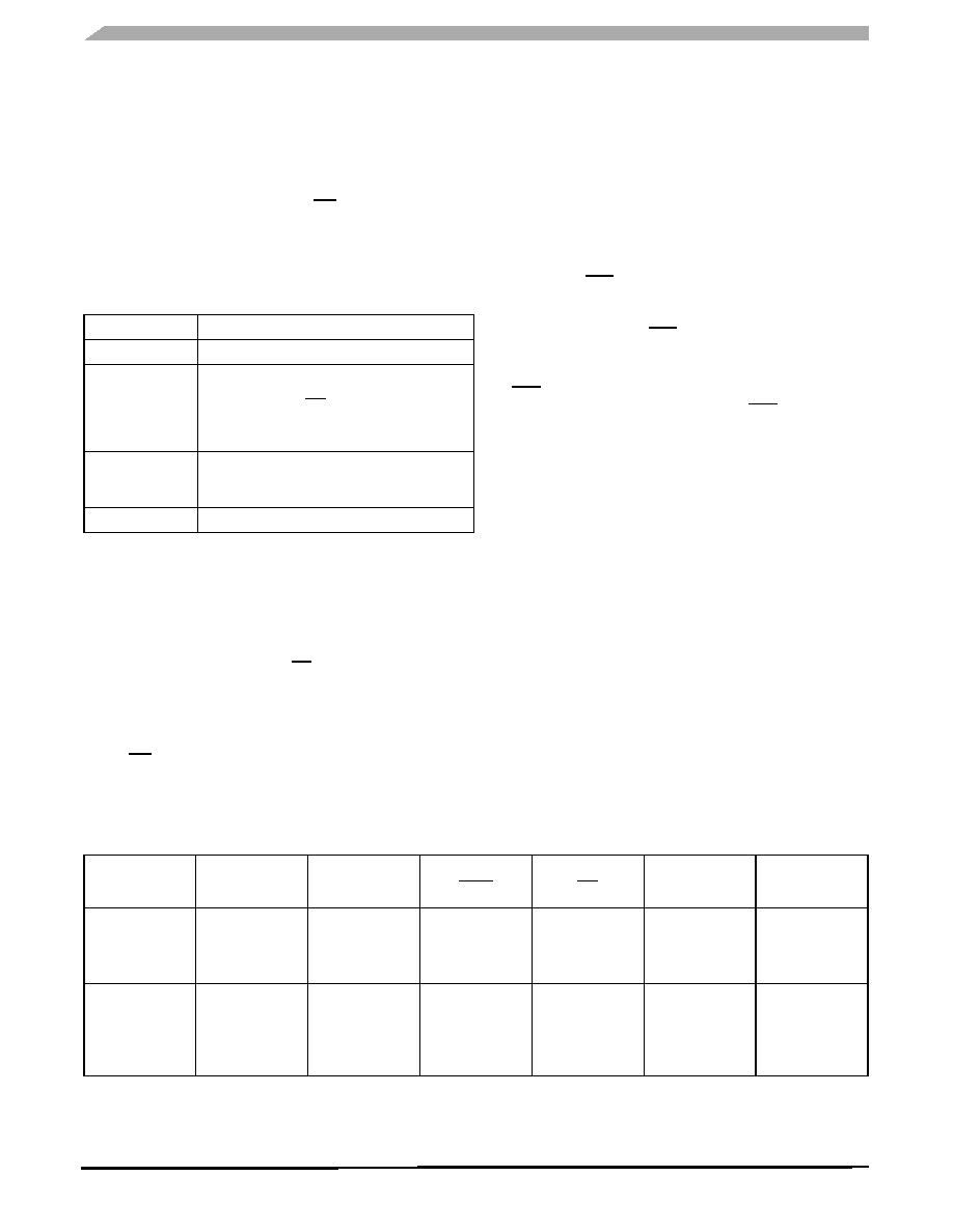
Figure 12. SBC Operation Mode
Table 15. SBC Mode vs. Local Wake-Up Behavior
SBC Modes
Local Wake-Up Behaviour
Normal Request
No Detection
Normal and
Stand-by
Detection Active According to the Option. The
Event is Stored in WUISR. The SBC may Activate
INT Output.
Real Time State of Each Wake-Up Input Pin
Available in WUIRTI Register
Sleep
Detection Active According to the Option. The
Event is Stored in WUISR. The SBC Switches to
Normal Request Mode
Emergency
No Detection
Mode
V1 & V2
Regulators, V3
Switch
Wake-Up
Capabilities
(if enabled)
Reset Pin
(RST)
Interrupt Pin
INT
Software
Watchdog
CAN Cell
Reset State
V1: ON (Unless
Failure Condition)
V2: OFF
V3:OFF
—
Low
(Duration 1 ms)
—
Term VBAT
Normal Request
V1: ON (75 ms
Timeout)
V2: OFF
V3: OFF
—
High
(Active Low -go to
Reset State if V1
Under Voltage
Occurs)
—
Term VBAT
相关PDF资料 |
PDF描述 |
|---|---|
| MC33388DR2 | IC TOLERANT CAN INT FAULT 14SOIC |
| PX0414 | CONN SMB JACK PNL MNT RG174 |
| PIC16LF1937-E/PT | IC PIC MCU FLASH 512KX14 44-TQFP |
| PIC16F1934-E/ML | IC PIC MCU FLASH 256KX7 44-QFN |
| V48C12M75B | CONVERTER MOD DC/DC 12V 75W |
相关代理商/技术参数 |
参数描述 |
|---|---|
| MC33389CDWR2 | 功能描述:网络控制器与处理器 IC SYSTEM BASIC CHIPS RoHS:否 制造商:Micrel 产品:Controller Area Network (CAN) 收发器数量: 数据速率: 电源电流(最大值):595 mA 最大工作温度:+ 85 C 安装风格:SMD/SMT 封装 / 箱体:PBGA-400 封装:Tray |
| MC33389DDW | 功能描述:网络控制器与处理器 IC SBC SOW28 RoHS:否 制造商:Micrel 产品:Controller Area Network (CAN) 收发器数量: 数据速率: 电源电流(最大值):595 mA 最大工作温度:+ 85 C 安装风格:SMD/SMT 封装 / 箱体:PBGA-400 封装:Tray |
| MC33389DDWR2 | 功能描述:网络控制器与处理器 IC SBC SOW28 RoHS:否 制造商:Micrel 产品:Controller Area Network (CAN) 收发器数量: 数据速率: 电源电流(最大值):595 mA 最大工作温度:+ 85 C 安装风格:SMD/SMT 封装 / 箱体:PBGA-400 封装:Tray |
| MC33390D | 功能描述:IC TRANSCEIVER SER LINK 8-SOIC RoHS:否 类别:集成电路 (IC) >> 接口 - 驱动器,接收器,收发器 系列:- 标准包装:1,000 系列:- 类型:收发器 驱动器/接收器数:2/2 规程:RS232 电源电压:3 V ~ 5.5 V 安装类型:表面贴装 封装/外壳:16-SOIC(0.295",7.50mm 宽) 供应商设备封装:16-SOIC 包装:带卷 (TR) |
| MC33390DR2 | 功能描述:IC TRANSCEIVER SER LINK 8-SOIC RoHS:否 类别:集成电路 (IC) >> 接口 - 驱动器,接收器,收发器 系列:- 标准包装:1,000 系列:- 类型:收发器 驱动器/接收器数:2/2 规程:RS232 电源电压:3 V ~ 5.5 V 安装类型:表面贴装 封装/外壳:16-SOIC(0.295",7.50mm 宽) 供应商设备封装:16-SOIC 包装:带卷 (TR) |
发布紧急采购,3分钟左右您将得到回复。