- 您现在的位置:买卖IC网 > PDF目录80570 > MC68HC11C0MFN2 (MOTOROLA INC) 8-BIT, 2 MHz, MICROCONTROLLER, PQCC68 PDF资料下载
参数资料
| 型号: | MC68HC11C0MFN2 |
| 厂商: | MOTOROLA INC |
| 元件分类: | 微控制器/微处理器 |
| 英文描述: | 8-BIT, 2 MHz, MICROCONTROLLER, PQCC68 |
| 封装: | PLASTIC, LCC-68 |
| 文件页数: | 76/76页 |
| 文件大小: | 394K |
| 代理商: | MC68HC11C0MFN2 |
第1页第2页第3页第4页第5页第6页第7页第8页第9页第10页第11页第12页第13页第14页第15页第16页第17页第18页第19页第20页第21页第22页第23页第24页第25页第26页第27页第28页第29页第30页第31页第32页第33页第34页第35页第36页第37页第38页第39页第40页第41页第42页第43页第44页第45页第46页第47页第48页第49页第50页第51页第52页第53页第54页第55页第56页第57页第58页第59页第60页第61页第62页第63页第64页第65页第66页第67页第68页第69页第70页第71页第72页第73页第74页第75页当前第76页
MC68HC11C0
MOTOROLA
MC68HC11C0TS/D
9
are located in internal RAM at locations $04C4–$04FD. The bootstrap ROM contains a small program
which initializes the SCI and allows the user to download a program of up to 256 bytes into on-chip
RAM. The program must begin at $0400. After an idle time of four-characters, or after receiving the
character for address $04FF, control passes to the loaded program at $0400. Refer to the memory map
diagram.
2.4 Special Test Mode
Special test mode is similar to expanded mode and is used primarily for production testing. The 1024-
byte bootstrap ROM is enabled and present at locations $FC00–$FFFF. In this operating mode, vectors
are fetched from external locations $BFC0–$BFFF.
2.5 Mode Selection
Although it is intended primarily for operation in expanded mode, the MC68HC11C0 has four possible
operating modes. The MC68HC11C0 can be reset to either expanded mode or special-test mode. The
initial operating mode is determined by the logic level present on the MODB pin during reset. After reset,
the operating mode may be changed according to the table contained in the following description of the
HPRIO register.
The function of internal read visibility/not E is determined by the state of the IRVNE bit and the mode
selected. When enabled, internal read visibility (IRV) causes the data from internal reads to be driven
out the data bus. The user must be cautioned that even though the R/W line suggests that the data bus
is in a high-impedance state, data will be driven out each time an internal read occurs. The not E clock
(NE) function of this bit determines whether the E clock is on or off. Refer to the description of IRVNE
in the OPT2 register.
*The reset value of SMOD depends on the logic level present on the MODB pin at the rising edge of reset.
RBOOT — Read Bootstrap ROM
Valid only when SMOD is set (bootstrap or special test mode). Resets to logic one in bootstrap mode
only. Can only be written in special modes.
0 = Bootloader ROM disabled and not in map
1 = Bootloader ROM enabled and in map at $BE00–$BFFF
SMOD and MDA — Special Mode Select and Mode Select A
The initial value of SMOD is the inverse of the logic level present on the MODB pin at the rising edge
of reset. The reset value of MDA is one. The value of MDA determines which operating mode is selected
after reset. These two bits can be read at any time. They can be written anytime in test modes (SMOD
= 1). MDA can only be written once in normal modes. SMOD cannot be set once it has been cleared.
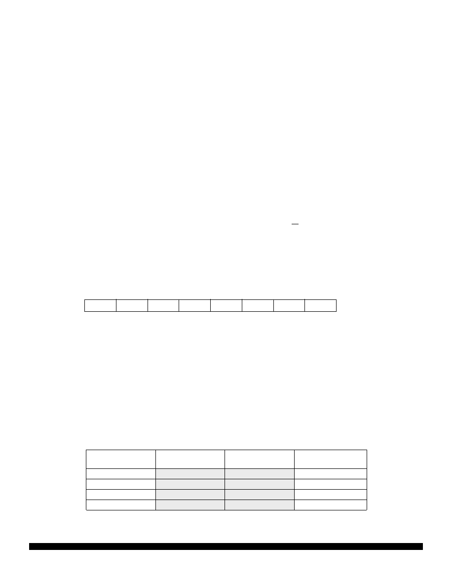
HPRIO — Highest Priority I-Bit Interrupt and Miscellaneous
$003C
Bit 7
654321
Bit 0
RBOOT
SMOD*
MDA
—
PSEL3
PSEL2
PSEL1
PSEL0
RESET:
0
—
100101
Logic Level of
MODB Pin at Reset
Value of SMOD
Latched at Reset
Programmed
Value of MDA
Mode Selected
1
0
1
Expanded
0
1
Special Test
1
0
Single Chip
0
1
0
Bootstrap
相关PDF资料 |
PDF描述 |
|---|---|
| MC68HC708AS60CFN | 8-BIT, FLASH, MICROCONTROLLER, PQCC52 |
| MC68HC05E1DWR2 | 8-BIT, MROM, 2.1 MHz, MICROCONTROLLER, PDSO28 |
| MC68HC05P6P | 8-BIT, MROM, 2.1 MHz, MICROCONTROLLER, PDIP28 |
| MSU2958C25-009J | 8-BIT, FLASH, 25 MHz, MICROCONTROLLER, PQCC44 |
| MSU2958C16-010U | 8-BIT, FLASH, 16 MHz, MICROCONTROLLER, PQFP44 |
相关代理商/技术参数 |
参数描述 |
|---|---|
| MC68HC11C0MFU2 | 制造商:FREESCALE 制造商全称:Freescale Semiconductor, Inc 功能描述:8-Bit Microcontroller |
| MC68HC11C0VFN2 | 制造商:FREESCALE 制造商全称:Freescale Semiconductor, Inc 功能描述:8-Bit Microcontroller |
| MC68HC11C0VFU2 | 制造商:FREESCALE 制造商全称:Freescale Semiconductor, Inc 功能描述:8-Bit Microcontroller |
| MC68HC11D0 | 制造商:FREESCALE 制造商全称:Freescale Semiconductor, Inc 功能描述:Microcontrollers |
| MC68HC11D0CFB2 | 制造商:Rochester Electronics LLC 功能描述:8BIT MCU,192 BYTES RAM - Bulk 制造商:Freescale Semiconductor 功能描述: 制造商:Motorola Inc 功能描述: 制造商:MOTOROLA 功能描述: |
发布紧急采购,3分钟左右您将得到回复。