- 您现在的位置:买卖IC网 > PDF目录11599 > MCP2510-I/SO (Microchip Technology)IC CAN CONTRLER IND TEMP 18SOIC PDF资料下载
参数资料
| 型号: | MCP2510-I/SO |
| 厂商: | Microchip Technology |
| 文件页数: | 44/80页 |
| 文件大小: | 0K |
| 描述: | IC CAN CONTRLER IND TEMP 18SOIC |
| 产品培训模块: | CAN Bus Protection |
| 标准包装: | 42 |
| 控制器类型: | CAN 接口 |
| 接口: | SPI |
| 电源电压: | 3 V ~ 5.5 V |
| 电流 - 电源: | 10mA |
| 工作温度: | -40°C ~ 85°C |
| 安装类型: | 表面贴装 |
| 封装/外壳: | 18-SOIC(0.295",7.50mm 宽) |
| 供应商设备封装: | 18-SOIC |
| 包装: | 管件 |
| 产品目录页面: | 685 (CN2011-ZH PDF) |
| 配用: | DV251001-ND - KIT DEVELOPMENT CAN MCP2510 |
第1页第2页第3页第4页第5页第6页第7页第8页第9页第10页第11页第12页第13页第14页第15页第16页第17页第18页第19页第20页第21页第22页第23页第24页第25页第26页第27页第28页第29页第30页第31页第32页第33页第34页第35页第36页第37页第38页第39页第40页第41页第42页第43页当前第44页第45页第46页第47页第48页第49页第50页第51页第52页第53页第54页第55页第56页第57页第58页第59页第60页第61页第62页第63页第64页第65页第66页第67页第68页第69页第70页第71页第72页第73页第74页第75页第76页第77页第78页第79页第80页
2007 Microchip Technology Inc.
DS21291F-page 49
MCP2510
8.0
OSCILLATOR
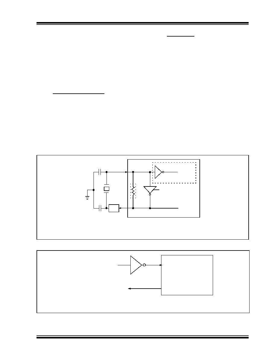
The MCP2510 is designed to be operated with a crystal
or ceramic resonator connected to the OSC1 and
OSC2 pins. The MCP2510 oscillator design requires
the use of a parallel cut crystal. Use of a series cut crys-
tal may give a frequency out of the crystal manufactur-
ers specifications. A typical oscillator circuit is shown in
Figure 8-1. The MCP2510 may also be driven by an
external clock source connected to the OSC1 pin as
shown in Figure 8-2 and Figure 8-3.
8.1
Oscillator Startup Timer
The MCP2510 utilizes an oscillator startup timer (OST),
which holds the MCP2510 in reset, to insure that the
oscillator has stabilized before the internal state
machine begins to operate. The OST maintains reset
for the first 128 OSC1 clock cycles after power up,
RESET, or wake up from sleep mode occurs. It should
be noted that no SPI operations should be attempted
until after the OST has expired.
8.2
CLKOUT Pin
The clock out pin is provided to the system designer for
use as the main system clock or as a clock input for
other devices in the system. The CLKOUT has an inter-
nal prescaler which can divide FOSC by 1, 2, 4 and 8.
The CLKOUT function is enabled and the prescaler is
selected via the CANCNTRL register (see Register 9-
1). The CLKOUT pin will be active upon system reset
and default to the slowest speed (divide by 8) so that it
can be used as the MCU clock. When sleep mode is
requested, the MCP2510 will drive sixteen additional
clock cycles on the CLKOUT pin before entering sleep
mode. The idle state of the CLKOUT pin in sleep mode
is low. When the CLKOUT function is disabled (CAN-
CNTRL.CLKEN = ‘0’) the CLKOUT pin is in a high
impedance state.
The CLKOUT function is designed to guarantee that
thCLKOUT and tlCLKOUT timings are preserved when the
CLKOUT pin function is enabled, disabled, or the pres-
caler value is changed.
FIGURE 8-1:
CRYSTAL/CERAMIC RESONATOR OPERATION
FIGURE 8-2:
EXTERNAL CLOCK SOURCE
C1
C2
XTAL
OSC2
RS(1)
OSC1
RF(2)
SLEEP
To internal logic
Note 1:
A series resistor, RS, may be required for AT strip cut crystals.
Note 2:
The feedback resistor, RF , is typically in the range of 2 to 10 M
Ω.
Clock from
external system
OSC1
OSC2
Open
(1)
Note 1:
A resistor to ground may be used to reduce system noise. This may increase system current.
Note 2:
Duty cycle restrictions must be observed (see Table 12-2).
相关PDF资料 |
PDF描述 |
|---|---|
| V48C28M75BF | CONVERTER MOD DC/DC 28V 75W |
| V48C28M75BL3 | CONVERTER MOD DC/DC 28V 75W |
| D38999/20MJ7SN | CONN RCPT 99POS WALL MNT W/SCKT |
| D38999/20JJ7SN | CONN RCPT 99POS WALL MNT W/SCKT |
| V48C24M75BL | CONVERTER MOD DC/DC 24V 75W |
相关代理商/技术参数 |
参数描述 |
|---|---|
| MCP2510-IST | 制造商:MICROCHIP 制造商全称:Microchip Technology 功能描述:Stand-Alone CAN Controller with SPI Interface |
| MCP2510I-ST | 制造商:MICROCHIP 制造商全称:Microchip Technology 功能描述:Stand-Alone CAN Controller with SPIa?¢ Interface |
| MCP2510T-/P | 制造商:MICROCHIP 制造商全称:Microchip Technology 功能描述:Stand-Alone CAN Controller with SPI⑩ Interface |
| MCP2510T-/SO | 制造商:MICROCHIP 制造商全称:Microchip Technology 功能描述:Stand-Alone CAN Controller with SPI⑩ Interface |
| MCP2510T-/ST | 制造商:MICROCHIP 制造商全称:Microchip Technology 功能描述:Stand-Alone CAN Controller with SPI⑩ Interface |
发布紧急采购,3分钟左右您将得到回复。