- 您现在的位置:买卖IC网 > PDF目录11599 > MCP2510-I/SO (Microchip Technology)IC CAN CONTRLER IND TEMP 18SOIC PDF资料下载
参数资料
| 型号: | MCP2510-I/SO |
| 厂商: | Microchip Technology |
| 文件页数: | 56/80页 |
| 文件大小: | 0K |
| 描述: | IC CAN CONTRLER IND TEMP 18SOIC |
| 产品培训模块: | CAN Bus Protection |
| 标准包装: | 42 |
| 控制器类型: | CAN 接口 |
| 接口: | SPI |
| 电源电压: | 3 V ~ 5.5 V |
| 电流 - 电源: | 10mA |
| 工作温度: | -40°C ~ 85°C |
| 安装类型: | 表面贴装 |
| 封装/外壳: | 18-SOIC(0.295",7.50mm 宽) |
| 供应商设备封装: | 18-SOIC |
| 包装: | 管件 |
| 产品目录页面: | 685 (CN2011-ZH PDF) |
| 配用: | DV251001-ND - KIT DEVELOPMENT CAN MCP2510 |
第1页第2页第3页第4页第5页第6页第7页第8页第9页第10页第11页第12页第13页第14页第15页第16页第17页第18页第19页第20页第21页第22页第23页第24页第25页第26页第27页第28页第29页第30页第31页第32页第33页第34页第35页第36页第37页第38页第39页第40页第41页第42页第43页第44页第45页第46页第47页第48页第49页第50页第51页第52页第53页第54页第55页当前第56页第57页第58页第59页第60页第61页第62页第63页第64页第65页第66页第67页第68页第69页第70页第71页第72页第73页第74页第75页第76页第77页第78页第79页第80页
MCP2510
DS21291F-page 6
2007 Microchip Technology Inc.
1.3
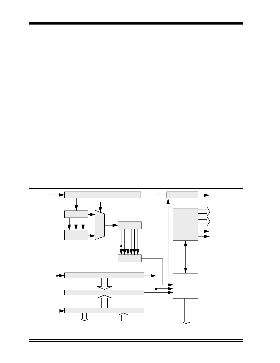
CAN Protocol Engine
The CAN protocol engine combines several functional
blocks, shown in Figure 1-4. These blocks and their
functions are described below.
1.4
Protocol Finite State Machine
The heart of the engine is the Finite State Machine
(FSM). This state machine sequences through mes-
sages on a bit by bit basis, changing states as the fields
of the various frame types are transmitted or received.
The FSM is a sequencer controlling the sequential data
stream between the TX/RX Shift Register, the CRC
Register, and the bus line. The FSM also controls the
Error Management Logic (EML) and the parallel data
stream between the TX/RX Shift Registers and the
buffers. The FSM insures that the processes of recep-
tion, arbitration, transmission, and error signaling are
performed according to the CAN protocol. The auto-
matic retransmission of messages on the bus line is
also handled by the FSM.
1.5
Cyclic Redundancy Check
The Cyclic Redundancy Check Register generates the
Cyclic Redundancy Check (CRC) code which is trans-
mitted after either the Control Field (for messages with
0 data bytes) or the Data Field, and is used to check the
CRC field of incoming messages.
1.6
Error Management Logic
The Error Management Logic is responsible for the
fault confinement of the CAN device. Its two counters,
the Receive Error Counter (REC) and the Transmit
Error Counter (TEC), are incremented and decre-
mented by commands from the Bit Stream Processor.
According to the values of the error counters, the CAN
controller is set into the states error-active, error-pas-
sive or bus-off.
1.7
Bit Timing Logic
The Bit Timing Logic (BTL) monitors the bus line input
and handles the bus related bit timing according to the
CAN protocol. The BTL synchronizes on a recessive to
dominant bus transition at Start of Frame (hard syn-
chronization) and on any further recessive to dominant
bus line transition if the CAN controller itself does not
transmit a dominant bit (resynchronization). The BTL
also provides programmable time segments to com-
pensate for the propagation delay time, phase shifts,
and to define the position of the Sample Point within the
bit time. The programming of the BTL depends upon
the baud rate and external physical delay times.
FIGURE 1-4:
CAN PROTOCOL ENGINE BLOCK DIAGRAM
Bit Timing Logic
CRC<14:0>
Comparator
Receive<7:0>
Transmit<7:0>
Sample<2:0>
Majority
Decision
StuffReg<5:0>
Comparator
Transmit Logic
Receive
Error Counter
Transmit
Error Counter
Protocol
FSM
RX
SAM
BusMon
Rec/Trm Addr.
RecData<7:0>
TrmData<7:0>
Shift<14:0>
(Transmit<5:0>, Receive<7:0>)
TX
REC
TEC
ErrPas
BusOff
Interface to Standard Buffer
相关PDF资料 |
PDF描述 |
|---|---|
| V48C28M75BF | CONVERTER MOD DC/DC 28V 75W |
| V48C28M75BL3 | CONVERTER MOD DC/DC 28V 75W |
| D38999/20MJ7SN | CONN RCPT 99POS WALL MNT W/SCKT |
| D38999/20JJ7SN | CONN RCPT 99POS WALL MNT W/SCKT |
| V48C24M75BL | CONVERTER MOD DC/DC 24V 75W |
相关代理商/技术参数 |
参数描述 |
|---|---|
| MCP2510-IST | 制造商:MICROCHIP 制造商全称:Microchip Technology 功能描述:Stand-Alone CAN Controller with SPI Interface |
| MCP2510I-ST | 制造商:MICROCHIP 制造商全称:Microchip Technology 功能描述:Stand-Alone CAN Controller with SPIa?¢ Interface |
| MCP2510T-/P | 制造商:MICROCHIP 制造商全称:Microchip Technology 功能描述:Stand-Alone CAN Controller with SPI⑩ Interface |
| MCP2510T-/SO | 制造商:MICROCHIP 制造商全称:Microchip Technology 功能描述:Stand-Alone CAN Controller with SPI⑩ Interface |
| MCP2510T-/ST | 制造商:MICROCHIP 制造商全称:Microchip Technology 功能描述:Stand-Alone CAN Controller with SPI⑩ Interface |
发布紧急采购,3分钟左右您将得到回复。