- 您现在的位置:买卖IC网 > PDF目录45317 > MD83C154CXXX-16P883D (TEMIC SEMICONDUCTORS) 8-BIT, MROM, 16 MHz, MICROCONTROLLER, CDIP40 PDF资料下载
参数资料
| 型号: | MD83C154CXXX-16P883D |
| 厂商: | TEMIC SEMICONDUCTORS |
| 元件分类: | 微控制器/微处理器 |
| 英文描述: | 8-BIT, MROM, 16 MHz, MICROCONTROLLER, CDIP40 |
| 文件页数: | 141/242页 |
| 文件大小: | 61013K |
| 代理商: | MD83C154CXXX-16P883D |
第1页第2页第3页第4页第5页第6页第7页第8页第9页第10页第11页第12页第13页第14页第15页第16页第17页第18页第19页第20页第21页第22页第23页第24页第25页第26页第27页第28页第29页第30页第31页第32页第33页第34页第35页第36页第37页第38页第39页第40页第41页第42页第43页第44页第45页第46页第47页第48页第49页第50页第51页第52页第53页第54页第55页第56页第57页第58页第59页第60页第61页第62页第63页第64页第65页第66页第67页第68页第69页第70页第71页第72页第73页第74页第75页第76页第77页第78页第79页第80页第81页第82页第83页第84页第85页第86页第87页第88页第89页第90页第91页第92页第93页第94页第95页第96页第97页第98页第99页第100页第101页第102页第103页第104页第105页第106页第107页第108页第109页第110页第111页第112页第113页第114页第115页第116页第117页第118页第119页第120页第121页第122页第123页第124页第125页第126页第127页第128页第129页第130页第131页第132页第133页第134页第135页第136页第137页第138页第139页第140页当前第141页第142页第143页第144页第145页第146页第147页第148页第149页第150页第151页第152页第153页第154页第155页第156页第157页第158页第159页第160页第161页第162页第163页第164页第165页第166页第167页第168页第169页第170页第171页第172页第173页第174页第175页第176页第177页第178页第179页第180页第181页第182页第183页第184页第185页第186页第187页第188页第189页第190页第191页第192页第193页第194页第195页第196页第197页第198页第199页第200页第201页第202页第203页第204页第205页第206页第207页第208页第209页第210页第211页第212页第213页第214页第215页第216页第217页第218页第219页第220页第221页第222页第223页第224页第225页第226页第227页第228页第229页第230页第231页第232页第233页第234页第235页第236页第237页第238页第239页第240页第241页第242页
225
ATmega165A/PA/325A/PA/3250A/PA/645A/P/6450A/P [DATASHEET]
8285E–AVR–02/2013
Note:
1. Incorrect setting of the switches in Figure 25-9 on page 223 will make signal contention and may damage the part.
There are several input choices to the S&H circuitry on the negative input of the output comparator in Figure 25-9
on page 223. Make sure only one path is selected from either one ADC pin, Bandgap reference source, or Ground.
If the ADC is not to be used during scan, the recommended input values from Table 25-3 on page 223 should be
used. The user is recommended not to use the Differential Amplifier during scan. Switch-Cap based differential
amplifier requires fast operation and accurate timing which is difficult to obtain when used in a scan chain. Details
concerning operations of the differential amplifier is therefore not provided.
The AVR ADC is based on the analog circuitry shown in Figure 25-9 on page 223 with a successive approximation
algorithm implemented in the digital logic. When used in Boundary-scan, the problem is usually to ensure that an
applied analog voltage is measured within some limits. This can easily be done without running a successive
approximation algorithm: apply the lower limit on the digital DAC[9:0] lines, make sure the output from the compar-
ator is low, then apply the upper limit on the digital DAC[9:0] lines, and verify the output from the comparator to be
high.
The ADC need not be used for pure connectivity testing, since all analog inputs are shared with a digital port pin as
well.
When using the ADC, remember the following
The port pin for the ADC channel in use must be configured to be an input with pull-up disabled to avoid signal
contention
In Normal mode, a dummy conversion (consisting of 10 comparisons) is performed when enabling the ADC. The
user is advised to wait at least 200ns after enabling the ADC before controlling/observing any ADC signal, or
perform a dummy conversion before using the first result
The DAC values must be stable at the midpoint value 0x200 when having the HOLD signal low (Sample mode)
As an example, consider the task of verifying a 1.5V ±5% input signal at ADC channel 3 when the power supply is
5.0V and AREF is externally connected to V
CC.
The recommended values from Table 25-3 on page 223 are used unless other values are given in the algorithm in
Table 25-4 on page 226. Only the DAC and port pin values of the Scan Chain are shown. The column “Actions”
describes what JTAG instruction to be used before filling the Boundary-scan Register with the succeeding col-
umns. The verification should be done on the data scanned out when scanning in the data on the same row in the
table.
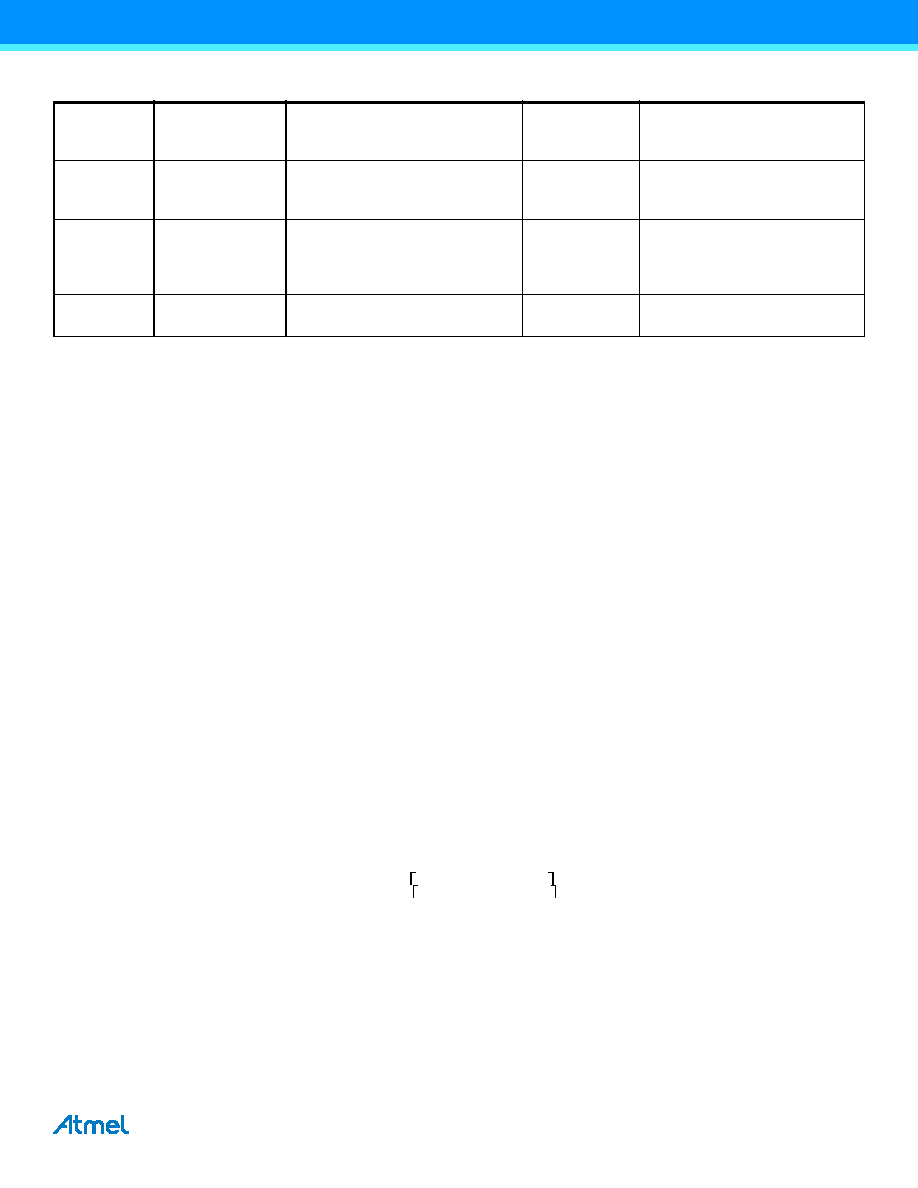
SCTEST
Input
Switch-cap TEST enable. Output
from differential amplifier is sent out
to Port Pin having ADC_4
00
ST
Input
Output of differential amplifier will
settle faster if this signal is high first
two ACLK periods after AMPEN
goes high.
00
VCCREN
Input
Selects Vcc as the ACC reference
voltage.
00
Table 25-3.
Boundary-scan Signals for the ADC
(1). (Continued)
Signal name
Direction as seen
from the ADC
Description
Recommended
Input when not
in use
Output values when
recommended inputs are used,
and CPU is not using the ADC
The lower limit is:
1024 1.5V 0,95 5V
291
0x123
==
The upper limit is:
1024 1.5V 1.05 5V
323
0x143
==
相关PDF资料 |
PDF描述 |
|---|---|
| MR83C154CXXX-L16P883 | 8-BIT, MROM, 16 MHz, MICROCONTROLLER, CQCC44 |
| MR83C154TXXX-L16P883D | 8-BIT, MROM, 16 MHz, MICROCONTROLLER, CQCC44 |
| MQ83C154XXX-20/883 | 8-BIT, MROM, 20 MHz, MICROCONTROLLER, CQFP44 |
| MR80C154-25/883D | 8-BIT, 25 MHz, MICROCONTROLLER, CQCC44 |
| MQ83C154XXX-30P883D | 8-BIT, MROM, 30 MHz, MICROCONTROLLER, CQFP44 |
相关代理商/技术参数 |
参数描述 |
|---|---|
| MD83C154-L16 | 制造商:TEMIC 制造商全称:TEMIC Semiconductors 功能描述:CMOS 0 to 36 MHz Single Chip 8-bit Microcontroller |
| MD83C154T-12 | 制造商:TEMIC 制造商全称:TEMIC Semiconductors 功能描述:CMOS 0 to 36 MHz Single Chip 8-bit Microcontroller |
| MD83C154T-16 | 制造商:TEMIC 制造商全称:TEMIC Semiconductors 功能描述:CMOS 0 to 36 MHz Single Chip 8-bit Microcontroller |
| MD83C154T-20 | 制造商:TEMIC 制造商全称:TEMIC Semiconductors 功能描述:CMOS 0 to 36 MHz Single Chip 8-bit Microcontroller |
| MD83C154T-25 | 制造商:TEMIC 制造商全称:TEMIC Semiconductors 功能描述:CMOS 0 to 36 MHz Single Chip 8-bit Microcontroller |
发布紧急采购,3分钟左右您将得到回复。