参数资料
| 型号: | NCN8024RDWR2G |
| 厂商: | ON Semiconductor |
| 文件页数: | 14/15页 |
| 文件大小: | 0K |
| 描述: | IC SMART CARD IC2 28SOIC |
| 标准包装: | 1,000 |
| 系列: | * |
NCN8024R
http://onsemi.com
8
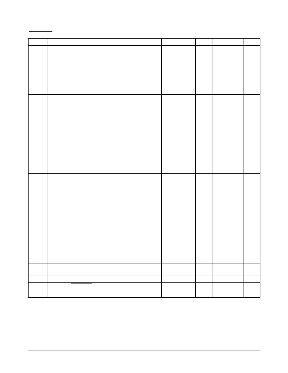
SMART CARD INTERFACE SECTION, CRD_IO, CRD_AUX1, CRD_AUX2, CRD_CLK, CRD_RST, CRD_PRES,
CRD_PRES (VDD = 3.3 V; VDDP = 5 V; Tamb = 25°C; FCLKIN = 10 MHz)
Symbol
Rating
Min
Typ
Max
Unit
VOH
VOL
VOH
VOL
tR
tF
td
CRD_RST @ CRD_VCC = 3.0 V, 5.0 V
Output RESET VOH @ Irst = 200 mA
Output RESET VOL @ Irst = 200 mA
Output RESET VOH @ Irst = 20 mA
Output RESET VOL @ Irst = 20 mA
RSTIN to CRD_RST Delay Reset Enabled (Note 7)
0.9 x CRD_VCC
0
CRD_VCC 0.4
CRD_VCC
0.20
0.4
CRD_VCC
100
2
V
ns
ms
FCRDCLK
VOH
VOL
VOH
VOL
FDC
trills
tulsa
SR
CRD_CLK @ CRD_VCC = 3.0 V or 5.0 V
Output Frequency (Note 7)
Output CRD_CLK VOH @ Iclk = 200 mA
Output CRD_CLK VOL @ Iclk = 200 mA
Output CRD_CLK VOH @ Iclk = 70 mA
Output CRD_CLK VOL @ Iclk = 70 mA
Output Duty Cycle (Note 7)
Rise & Fall time (Note 5)
Output CRD_CLK Risetime @ Cout = 30 pF
Output CRD_CLK Falltime @ Cout = 30 pF
Slew Rate @ Cout = 33 pF (Note 7)
0.9 x CRD_VCC
0
CRD_VCC 0.4
45
0.2
18
CRD_VCC
+0.2
0.4
CRD_VCC
55
16
MHz
V
%
ns
V/ns
VIH
VIL
IIL
IIH
VOH
VOL
tRi/Fi
tRo/Fo
CRD_AUX1, CRD_AUX2, CRD_IO @ CRD_VCC = 3.0 V, 5.0 V
Input Voltage High Level (5 V Mode)
Input Voltage High Level (3 V Mode)
Input Voltage Low Level
Low Level Input Current VIL = 0 V
High Level Input Current VIH = CRD_VCC
Output VOH
@ IOH = 40 mA
Output VOL
@ IOL = 1 mA, VIL = 0 V
Input Rising/Falling Times
Output Rising/Falling Times / Cout = 80 pF
2.3
1.6
0.30
0.75 x CRD_VCC
0
CRD_VCC+0.3
0.80
600
10
CRD_VCC+0.1
0.30
1.2
0.1
V
mA
V
ms
RPU
CRD_AUX1, CRD_AUX2, CRD_IO Pullup Resistor
8.0
11
16
kW
tIO
Propagation delay IOuc > CRD_IO and CRD_IO > IOuc (Falling
Edge) (Note 7)
200
ns
tpu
Active pullup pulse width buffers I/O, AUX1 & AUX2 (Note 7)
200
ns
VIH
VIL
CRD_PRES, CRD_PRES
Card Presence Voltage High Level
Card Presence Voltage Low Level
0.7 x VDD
0.3
VDD + 0.3
0.3 x VDD
V
NOTE: Device will meet the specifications after thermal equilibrium has been established when mounted in a test socket or printed
circuit board with maintained transverse airflow greater than 500 lfpm. Electrical parameters are guaranteed only over the
declared operating temperature range. Functional operation of the device exceeding these conditions is not implied. Device
specification limit values are applied individually under normal operating conditions and not valid simultaneously.
7. Guaranteed by design and characterization
相关PDF资料 |
PDF描述 |
|---|---|
| NCN8025MTTBG | IC SMART CARD I2C 16-QFN |
| NCN9252MUTAG | IC USB SWITCH DP3T 12UQFN |
| NCP1092DBRG | IC CTLR IEEE 802.3AF 8-TSSOP |
| NCP1094MNRG | IC INTERFACE CTLR POE-PD 10-DFN |
| NCS36000DG | IC PIR DETECTOR CTLR 14SOIC |
相关代理商/技术参数 |
参数描述 |
|---|---|
| NCN8025 | 制造商:ONSEMI 制造商全称:ON Semiconductor 功能描述:Compact SMART CARD Interface IC |
| NCN8025A-EVB | 制造商:ON Semiconductor 功能描述:Evaluation board for 1.8V/3V/5V Smart Card Interface 制造商:P&S 功能描述:Evaluation board for 1.8V/3V/5V Smart Card Interface |
| NCN8025AMNGEVB | 功能描述:电源管理IC开发工具 NCN8025AMNTXG RoHS:否 制造商:Maxim Integrated 产品:Evaluation Kits 类型:Battery Management 工具用于评估:MAX17710GB 输入电压: 输出电压:1.8 V |
| NCN8025AMNTXG | 功能描述:接口 - 专用 SMART CARD IC RoHS:否 制造商:Texas Instruments 产品类型:1080p60 Image Sensor Receiver 工作电源电压:1.8 V 电源电流:89 mA 最大功率耗散: 最大工作温度:+ 85 C 安装风格:SMD/SMT 封装 / 箱体:BGA-59 |
| NCN8025MTTBG | 功能描述:接口 - 专用 SMART CARD IC RoHS:否 制造商:Texas Instruments 产品类型:1080p60 Image Sensor Receiver 工作电源电压:1.8 V 电源电流:89 mA 最大功率耗散: 最大工作温度:+ 85 C 安装风格:SMD/SMT 封装 / 箱体:BGA-59 |
发布紧急采购,3分钟左右您将得到回复。