- 您现在的位置:买卖IC网 > Datasheet目录45 > NCP1083DEG (ON Semiconductor)IC CONV CTLR POE-PD 40W 20-TSSOP Datasheet资料下载
参数资料
| 型号: | NCP1083DEG |
| 厂商: | ON Semiconductor |
| 文件页数: | 13/18页 |
| 文件大小: | 257K |
| 描述: | IC CONV CTLR POE-PD 40W 20-TSSOP |
| 标准包装: | 74 |
| 类型: | 以太网供电开关(PoE) |
| 应用: | 远程外设(工业控制,相机,数据访问) |
| 内部开关: | 是 |
| 电流限制: | 1.1A |
| 电源电压: | 0 V ~ 57 V |
| 工作温度: | -40°C ~ 85°C |
| 安装类型: | 表面贴装 |
| 封装/外壳: | 20-TSSOP(0.173",4.40mm 宽)裸露焊盘 |
| 供应商设备封装: | 20-TSSOP-EP |
| 包装: | 管件 |
NCP1083
http://onsemi.com
13
" The PSE skipped the classification phase.
" The PSE performed a one event hardware classification
(it can be a IEEE 802.3af or a 802.3at compliant PSE
with Layer 2 engine).
" The PSE performed a two event hardware classification
but it did not properly control the input voltage in the
mark voltage window, (for example it crossed the reset
range).
Power Mode
When the classification handshake is completed, the
PSE and PD devices move into the operating mode.
Under Voltage Lock Out (UVLO)
The NCP1083 incorporates an under voltage lock out
(UVLO) circuit which monitors the input voltage and
determines when to apply power to the DCDC controller.
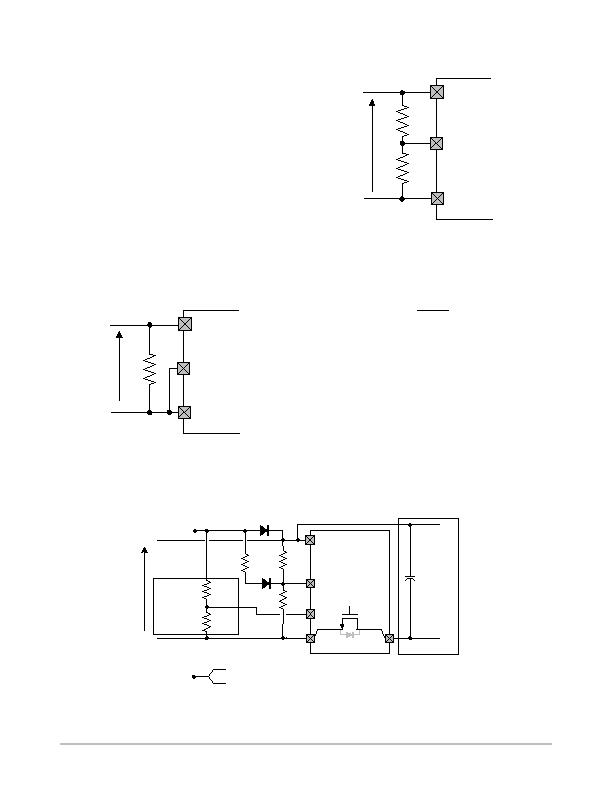
To use the default settings for UVLO (see Table 3), the pin
UVLO must be connected to VPORTN
1,2
. In this case the
signature resistor has to be placed directly between
VPORTP and VPORTN
1,2
, as shown in Figure 11.
Figure 11. Default UVLO Settings
UVLO
VPORTP
VPORTN1,2
NCP1083
VPORT
Rdet
To define the UVLO threshold externally, the UVLO pin
must be connected to the center of an external resistor
divider between VPORTP and VPORTN
1,2
as shown in
Figure 12. The series resistance value of the external
resistors must add to 25.5 kW and replaces the internal
signature resistor.
Figure 12. External UVLO Configuration
UVLO
VPORTN1,2
NCP1083
VPORT
R2
R1
VPORTP
For a Vuvlo_on desired turnon voltage threshold, R1 and
R2 can be calculated using the following equations:
R1 ) R2 + R
det
R2 +
1.2
V
ulvo_on
R
det
When using the external resistor divider, the NCP1083 has
an external reference voltage hysteresis of 15 percent typical.
Auxiliary Supply Support
To support applications connected to nonPoE enabled
networks and minimize the bill of materials, the NCP1083
supports drawing power from an external supply. The
NCP1083 supports the IEEE 802.3af/at standard when PoE
power sourcing is available and acts as a regular DCDC
converter when there is no power source available on the
Ethernet cable as shown in Figure 13.
Auxiliary supply support can be implemented in three
ways depending on where the auxiliary supply is injected.
The front, rear and direct auxiliary supply configurations are
explained in more detail in the application note AND9080.
UVLO
VPORTN1,2
NCP1083
VPORTP
Rdet1
Raux2
VAUX(+)
Rdet2
Pass
Switch
RTN
Raux1
Raux3
AUX
D1
D2
POE(+)
POE()
VPORT
Cpd
DCDC Stage
VAUX()
to VPORTN1,2 (Front AUX Configuration)
to RTN (Rear AUX Configuration)
Or
Figure 13. Front and Rear Auxiliary Supply Input with Support for Very Low Input Voltages
Optional
for very low
VAUX only
相关PDF资料 |
PDF描述 |
|---|---|
| NCP1501DMR2G | IC REG SGL BUCK/LINEAR 8MICRO |
| NCP1578MNR2G | IC REG DL BCK/LINEAR SYNC 20-QFN |
| NCP1601BDR2G | IC PFC CTRL CRM/TRANSITION 8SOIC |
| NCP1603D100R2G | IC CTLR PFC/PWM COMBO 16-SOIC |
| NCP1605DR2G | IC PFC CONTROLLER CCM/DCM 16SOIC |
相关代理商/技术参数 |
参数描述 |
|---|---|
| NCP1083DER2G | 功能描述:DC/DC 开关控制器 POE-PD 40W DC-DC AUX SUPP RoHS:否 制造商:Texas Instruments 输入电压:6 V to 100 V 开关频率: 输出电压:1.215 V to 80 V 输出电流:3.5 A 输出端数量:1 最大工作温度:+ 125 C 安装风格: 封装 / 箱体:CPAK |
| NCP1083QBCGEVB | 功能描述:电源管理IC开发工具 HIGH POWER POE-PD MODULE RoHS:否 制造商:Maxim Integrated 产品:Evaluation Kits 类型:Battery Management 工具用于评估:MAX17710GB 输入电压: 输出电压:1.8 V |
| NCP1083WIRGEVB | 功能描述:电源管理IC开发工具 POE-PD MODULE WITH VAUX RoHS:否 制造商:Maxim Integrated 产品:Evaluation Kits 类型:Battery Management 工具用于评估:MAX17710GB 输入电压: 输出电压:1.8 V |
| NCP1086 | 制造商:ONSEMI 制造商全称:ON Semiconductor 功能描述:1.5 A Adjustable and 3.3 V Fixed Output Linear Regulator |
| NCP1086/D | 制造商:未知厂家 制造商全称:未知厂家 功能描述:1.5 A Adjustable and 3.3 V Fixed Output Linear Regulator |
发布紧急采购,3分钟左右您将得到回复。