- 您现在的位置:买卖IC网 > PDF目录19522 > NCP1280DR2 (ON Semiconductor)IC CTRLR PWM PROG OVP HV 16SOIC PDF资料下载
参数资料
| 型号: | NCP1280DR2 |
| 厂商: | ON Semiconductor |
| 文件页数: | 13/17页 |
| 文件大小: | 0K |
| 描述: | IC CTRLR PWM PROG OVP HV 16SOIC |
| 标准包装: | 2,500 |
| 输出隔离: | 隔离 |
| 频率范围: | 140kHz ~ 320kHz |
| 输入电压: | 7 V ~ 25 V |
| 工作温度: | -40°C ~ 150°C |
| 封装/外壳: | 16-SOIC(0.154",3.90mm 宽) |
| 供应商设备封装: | 16-SOIC N |
| 包装: | 带卷 (TR) |
�� �
�
NCP1280�
�SOFT� ?� START�
�V� AUX(on)�
�V� AUX�
�V� AUX(off)�
�0V�
�2V�
�0V�
�0V�
�UV/OV� Voltage�
�Soft� ?� Start� Voltage�
�OUT2�
�0V�
�OUT1�
�0V�
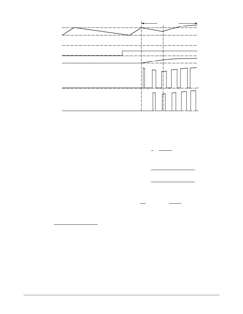
�Figure� 31.� Soft� ?� Start� Timing� Diagram� (Using� Auxiliary� Winding)�
�T� +� 1� +�
�+� 5.0� m� s�
�IFF� +�
�IFF� +�
�+� 55.2� m� A�
�+�
�RFF� +� in� *� 12.0� k� W� +�
�*� 12.0� k� W� [� 1.82� M� W�
�Feedforward� Ramp� Generator�
�The� NCP1280� incorporates� line� feedforward� (FF)� to�
�compensate� for� changes� in� line� voltage.� A� FF� Ramp�
�proportional� to� V� in� is� generated� and� compared� to� V� EA� .� If� the�
�line� voltage� changes,� the� FF� Ramp� slope� changes�
�accordingly.� The� duty� cycle� will� be� adjusted� immediately�
�instead� of� waiting� for� the� line� voltage� change� to� propagate�
�around� the� system� and� be� reflected� back� on� V� EA� .�
�A� resistor� between� V� in� and� the� FF� pin� (R� FF� )� sets� the�
�feedforward� current� (I� FF� ).� The� FF� Ramp� is� generated� by�
�charging� an� internal� 10� pF� capacitor� (C� FF� )� with� a� constant�
�current� proportional� to� I� FF� .� The� FF� Ramp� is� finished�
�(capacitor� is� discharged)� once� the� Oscillator� Ramp� reaches�
�2.0� V.� Please� refer� to� Figure� 2� for� a� functional� drawing� of� the�
�Feedforward� Ramp� generator.�
�I� FF� is� usually� a� few� hundred� microamps,� depending� on� the�
�operating� frequency� and� the� required� duty� cycle.� If� the�
�operating� frequency� and� maximum� duty� cycle� are� known,�
�I� FF� is� calculated� using� the� equation� below:�
�CFF VDC(inv) 125 k� W�
�6.7� k� W� ton(max)�
�where� V� DC(inv)� is� the� voltage� on� the� inverting� input� of� the�
�Max� DC� Comparator� and� t� on(max)� is� the� maximum� ON� time.�
�Figure� 18� shows� the� relationship� between� I� FF� and� DC� MAX� .�
�For� example,� if� a� system� is� designed� to� operate� at� 200� kHz,�
�with� a� 60%� maximum� duty� cycle� at� 100� V,� the� DC� MAX� pin�
�can� be� grounded� and� I� FF� is� calculated� as� follows:�
�1�
�f� 200� kHz�
�ton(max)� +� DCMAX� T� +� 0.6� 5.0� m� s� +� 3.0� m� s�
�CFF VDC(inv) 125 k� W�
�6.7� k� W� ton(max)�
�10 pF 0.888 V 125 k� W�
�6.7� k� W� 3.0� m� s�
�For� a� minimum� line� voltage� of� 100� V,� the� required�
�feedforward� resistor� is� calculated� using� the� equation� below:�
�V� 100� V�
�IFF� 55.2� m� A�
�From� the� above� calculations� it� can� be� observed� that� I� FF� is�
�controlled� predominantly� by� the� value� of� R� FF� ,� as� the�
�resistance� seen� into� the� FF� pin� is� only� 12� k� W� .� If� a� tight�
�maximum� duty� cycle� control� overtemperature� is� required,�
�R� FF� should� have� a� low� thermal� coefficient.�
�http://onsemi.com�
�13�
�相关PDF资料 |
PDF描述 |
|---|---|
| TCN75-3.3MOA | IC TEMP SENSOR SRL 3.3V 8SOIC |
| GSA49DTAN | CONN EDGECARD 98POS R/A .125 SLD |
| VE-27J-CY-F4 | CONVERTER MOD DC/DC 36V 50W |
| TC653BEVUATR | IC TEMP SNSR/DC FAN CNTRLR 8MSOP |
| GPM80PG | PS MEDICAL QUAD OUT +5,12,24,-12 |
相关代理商/技术参数 |
参数描述 |
|---|---|
| NCP1280DR2G | 功能描述:电压模式 PWM 控制器 Active Clamp Voltage Mode PWM RoHS:否 制造商:Texas Instruments 输出端数量:1 拓扑结构:Buck 输出电压:34 V 输出电流: 开关频率: 工作电源电压:4.5 V to 5.5 V 电源电流:600 uA 最大工作温度:+ 125 C 最小工作温度:- 40 C 封装 / 箱体:WSON-8 封装:Reel |
| NCP1282 | 制造商:ONSEMI 制造商全称:ON Semiconductor 功能描述:Power Factor Controllers |
| NCP1282BDR2G | 功能描述:电压模式 PWM 控制器 HI PRF RSET PWM CNTR RoHS:否 制造商:Texas Instruments 输出端数量:1 拓扑结构:Buck 输出电压:34 V 输出电流: 开关频率: 工作电源电压:4.5 V to 5.5 V 电源电流:600 uA 最大工作温度:+ 125 C 最小工作温度:- 40 C 封装 / 箱体:WSON-8 封装:Reel |
| NCP1288 | 制造商:ONSEMI 制造商全称:ON Semiconductor 功能描述:Fixed Frequency Current Mode Controller for Flyback Converters |
| NCP1288_11 | 制造商:ONSEMI 制造商全称:ON Semiconductor 功能描述:Fixed Frequency Current Mode Controller for Flyback Converters |
发布紧急采购,3分钟左右您将得到回复。