- 您现在的位置:买卖IC网 > PDF目录378049 > PGA309EVM (Texas Instruments, Inc.) PGA309 Evaluation Module(PGA309评估模块) PDF资料下载
参数资料
| 型号: | PGA309EVM |
| 厂商: | Texas Instruments, Inc. |
| 英文描述: | PGA309 Evaluation Module(PGA309评估模块) |
| 中文描述: | PGA309评估模块(PGA309评估模块) |
| 文件页数: | 31/53页 |
| 文件大小: | 4221K |
| 代理商: | PGA309EVM |
第1页第2页第3页第4页第5页第6页第7页第8页第9页第10页第11页第12页第13页第14页第15页第16页第17页第18页第19页第20页第21页第22页第23页第24页第25页第26页第27页第28页第29页第30页当前第31页第32页第33页第34页第35页第36页第37页第38页第39页第40页第41页第42页第43页第44页第45页第46页第47页第48页第49页第50页第51页第52页第53页
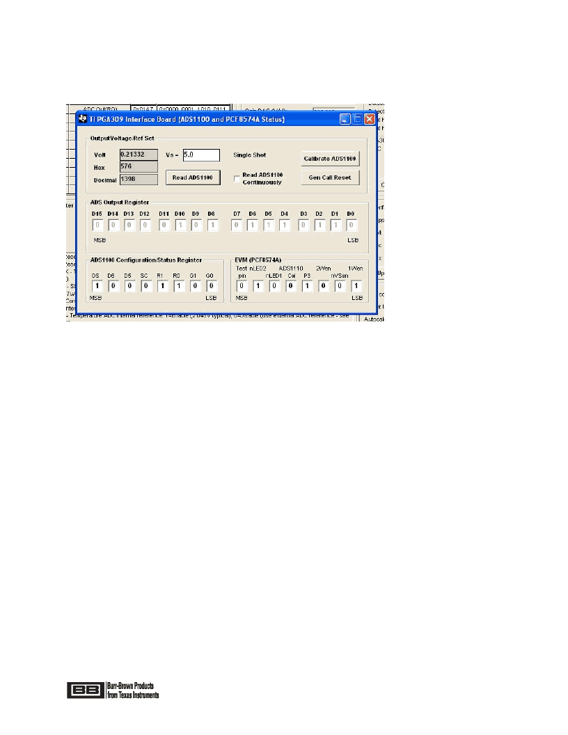
7.7 Interface Board and ADS1100
In the “Interface Board and ADS1100” section, in the Main Window, click on “Board Settings”. A pop-up
window will appear as in Figure 23. This pop-up window provides configuration control of the ADS1100 and
the Port Expander, PCF8574A.
Page 31 of 53
Figure 23: “ADS1100 and PCF8574A Status” Window
In the pop-up window the bits under “EVM (PCF8574A)” will toggle when single-clicked. Table 6 describes the
use of each of these bits.
If the “Calibrate ADS1100” Button is pushed it will short the two inputs of the ADS1100 together and compute
the offset error. All ADS1100 readings which follow will be calibrated to account for this offset error. In
addition measure the voltage Vs on the PGA309 PC Interface Board with an accurate meter and enter this
voltage in the “Supply Vcc (V)” box in the Main Window or enter this voltage into the “Vs=” box in the pop-up
window. After these two ADS1100 calibration steps are complete the ADS1100 is fully calibrated for both gain
and offset errors. Each time the “Calibrate ADS1100” Button is pushed a new ADS1100 offset calibration is
performed and the subsequent readings will use the latest calibration numbers.
If the “Read ADS1100” button is pushed a single conversion will be performed in the ADS1100. The reading
will be updated in both the Main Window and in the pop-up window. If the box labeled “Read ADS1100
Continuously” is checked then both the pop-up window and Main Window ADS1100 readings will be updated
about every 2 seconds depending upon the operating system conditions.
The “ADS Output Register” section in the pop-up window is a read-only bit readout of the latest ADS1110
conversion.
The “ADS1100 Configuration Status Register” bits allow for custom configuration of the ADS1100. These bits
are toggled by a one-click method in the corresponding box. The default setting is 0x8C. This configures the
ADS1100 for Continuous Conversion Mode, Internal PGA=x1, and 8 samples per second data rate. If these
settings are changed they can be returned to the initial power-up settings by pushing the “Gen Call Reset” in
the pop-up window. If the Vcc voltage on the PGA309 PC Interface Board is changed then the ADS1100 will
need to be re-calibrated for gain and offset (this assumes Vcc will become the Vs for the PGA309 Sensor
Interface Board). For further ADS1100 details consult the ADS1100 data sheet.
相关PDF资料 |
PDF描述 |
|---|---|
| PGE60801 | Erbium-Doped Fiber Amplifier for Digital Applications |
| PGE60802 | Erbium-Doped Fiber Amplifier for Digital Applications |
| PGE60803 | Erbium-Doped Fiber Amplifier for Digital Applications |
| PGE60816 | EDFA Gain Block for DWDM Applications |
| PGE60817 | EDFA Gain Block for DWDM Applications |
相关代理商/技术参数 |
参数描述 |
|---|---|
| PGA309EVM-EU | 功能描述:光学传感器开发工具 PGA309 Eval Mod- Wldwide RoHS:否 制造商:ams 工具用于评估: 接口类型: 最大工作温度: |
| PGA309EVM-US | 功能描述:光学传感器开发工具 PGA309 Eval Mod- US & Canada RoHS:否 制造商:ams 工具用于评估: 接口类型: 最大工作温度: |
| PGA309EVM-USB | 功能描述:放大器 IC 开发工具 PGA309 Eval Mod RoHS:否 制造商:International Rectifier 产品:Demonstration Boards 类型:Power Amplifiers 工具用于评估:IR4302 工作电源电压:13 V to 23 V |
| PGA309EVM-USB | 制造商:Texas Instruments 功能描述:ANALOG SIGNAL CONDITIONING EVAL. MODULE |
| PGA309-HT | 制造商:TI 制造商全称:Texas Instruments 功能描述:VOLTAGE OUTPUT PROGRAMMABLE SENSOR CONDITIONER |
发布紧急采购,3分钟左右您将得到回复。