- 您现在的位置:买卖IC网 > PDF目录299771 > PIC16C923T-04I/PT 8-BIT, OTPROM, 4 MHz, RISC MICROCONTROLLER, PQFP64 PDF资料下载
参数资料
| 型号: | PIC16C923T-04I/PT |
| 元件分类: | 微控制器/微处理器 |
| 英文描述: | 8-BIT, OTPROM, 4 MHz, RISC MICROCONTROLLER, PQFP64 |
| 封装: | 10 X 10 MM, 1 MM HEIGHT, PLASTIC, TQFP-64 |
| 文件页数: | 147/189页 |
| 文件大小: | 1201K |
| 代理商: | PIC16C923T-04I/PT |
第1页第2页第3页第4页第5页第6页第7页第8页第9页第10页第11页第12页第13页第14页第15页第16页第17页第18页第19页第20页第21页第22页第23页第24页第25页第26页第27页第28页第29页第30页第31页第32页第33页第34页第35页第36页第37页第38页第39页第40页第41页第42页第43页第44页第45页第46页第47页第48页第49页第50页第51页第52页第53页第54页第55页第56页第57页第58页第59页第60页第61页第62页第63页第64页第65页第66页第67页第68页第69页第70页第71页第72页第73页第74页第75页第76页第77页第78页第79页第80页第81页第82页第83页第84页第85页第86页第87页第88页第89页第90页第91页第92页第93页第94页第95页第96页第97页第98页第99页第100页第101页第102页第103页第104页第105页第106页第107页第108页第109页第110页第111页第112页第113页第114页第115页第116页第117页第118页第119页第120页第121页第122页第123页第124页第125页第126页第127页第128页第129页第130页第131页第132页第133页第134页第135页第136页第137页第138页第139页第140页第141页第142页第143页第144页第145页第146页当前第147页第148页第149页第150页第151页第152页第153页第154页第155页第156页第157页第158页第159页第160页第161页第162页第163页第164页第165页第166页第167页第168页第169页第170页第171页第172页第173页第174页第175页第176页第177页第178页第179页第180页第181页第182页第183页第184页第185页第186页第187页第188页第189页
PIC16C9XX
DS30444E - page 60
1997 Microchip Technology Inc.
10.3.2
PWM DUTY CYCLE
The PWM duty cycle is specied by writing to the
CCPR1L register and to the CCP1CON<5:4> bits. Up
to 10-bit resolution is available: the CCPR1L contains
the eight MSbs and CCP1CON<5:4> contains the two
LSbs.
This
10-bit
value
is
represented
by
CCPR1L:CCP1CON<5:4>. The following equation is
used to calculate the PWM duty cycle in time:
PWM duty cycle = (CCPR1L:CCP1CON<5:4>)
Tosc (TMR2 prescale value)
CCPR1L and CCP1CON<5:4> can be written to at any
time, but the duty cycle value is not latched into
CCPR1H until after a match between PR2 and TMR2
occurs (i.e., the period is complete). In PWM mode,
CCPR1H is a read-only register.
The CCPR1H register and a 2-bit internal latch are
used to double buffer the PWM duty cycle. This double
buffering is essential for glitchless PWM operation.
When the CCPR1H and 2-bit latch match TMR2 con-
catenated with an internal 2-bit Q clock or 2 bits of the
TMR2 prescaler, the CCP1 pin is cleared.
Maximum PWM resolution (bits) for a given PWM fre-
quency:
Note:
The Timer2 postscaler (Section 9.0) is not
used in the determination of the PWM fre-
quency. The postscaler could be used to
have a servo update rate at a different fre-
quency than the PWM output.
Note:
If the PWM duty cycle value is longer than
the PWM period the CCP1 pin will not be
cleared.
log
(
FPWM
log(2)
FOSC
)
bits
=
EXAMPLE 10-2: PWM PERIOD AND DUTY
CYCLE CALCULATION
Desired PWM frequency is 31.25 kHz,
Fosc = 8 MHz
TMR2 prescale = 1
1/31.25 kHz
= [ (PR2) + 1 ] 4 1/8 MHz 1
32
s
= [ (PR2) + 1 ] 4 125 ns 1
PR2
= 63
Find the maximum resolution of the duty cycle that can
be used with a 31.25 kHz frequency and 8 MHz oscilla-
tor:
1/31.25 kHz
= 2
PWM RESOLUTION 1/8 MHz 1
32
s
= 2
PWM RESOLUTION 125 ns 1
256
= 2
PWM RESOLUTION
log(256)
= (PWM Resolution) log(2)
8.0
= PWM Resolution
At most, an 8-bit resolution duty cycle can be obtained
from a 31.25 kHz frequency and a 8 MHz oscillator, i.e.,
0
≤ CCPR1L:CCP1CON<5:4> ≤ 255. Any value greater
than 255 will result in a 100% duty cycle.
In order to achieve higher resolution, the PWM fre-
quency must be decreased. In order to achieve higher
PWM frequency, the resolution must be decreased.
Table 10-2 lists example PWM frequencies and resolu-
tions for Fosc = 8 MHz. TMR2 prescaler and PR2 val-
ues are also shown.
10.3.3
SET-UP FOR PWM OPERATION
The following steps should be taken when conguring
the CCP module for PWM operation:
1.
Set the PWM period by writing to the PR2 regis-
ter.
2.
Set the PWM duty cycle by writing to the
CCPR1L register and CCP1CON<5:4> bits.
3.
Make the CCP1 pin an output by clearing the
TRISC<2> bit.
4.
Set the TMR2 prescale value and enable Timer2
by writing to T2CON.
5.
Congure the CCP module for PWM operation.
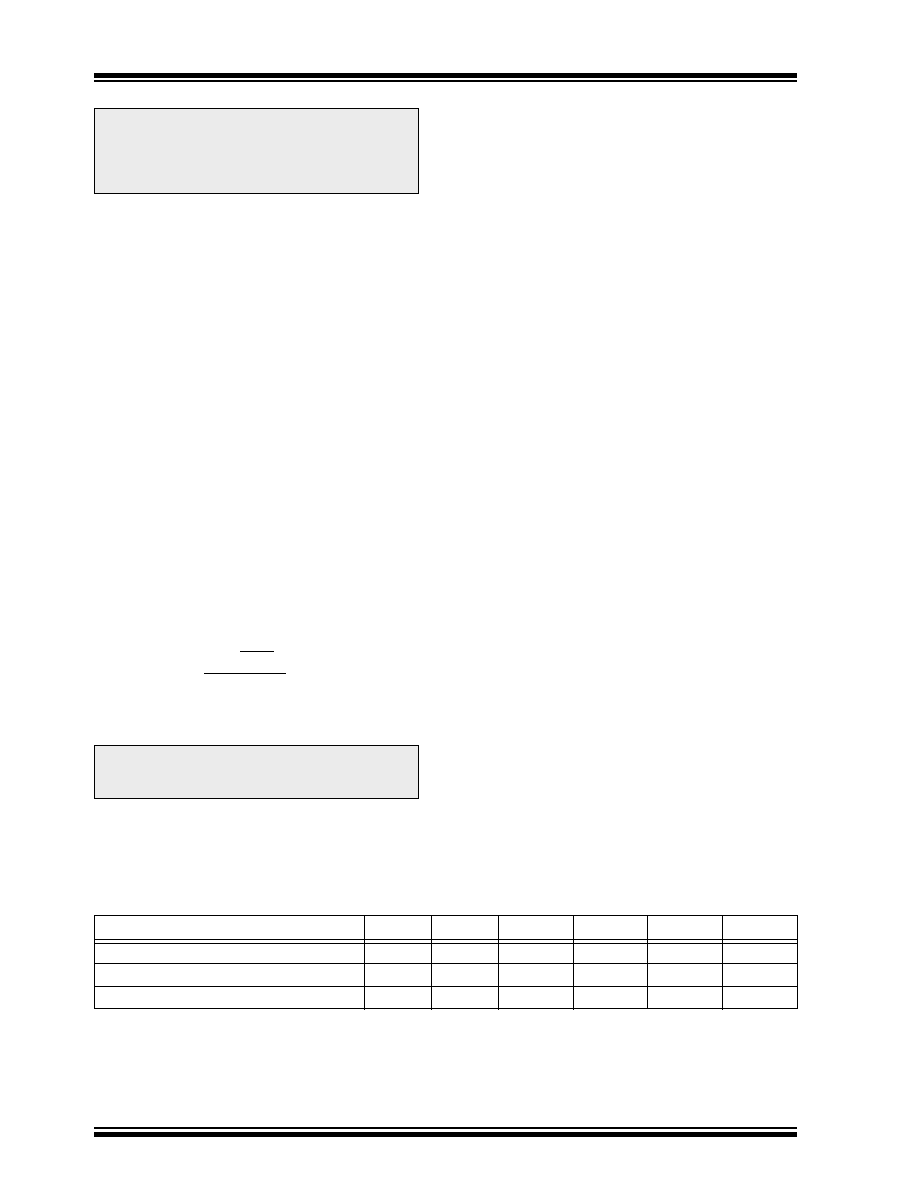
TABLE 10-2: EXAMPLE PWM FREQUENCIES AND RESOLUTIONS AT 8 MHz
PWM Frequency
488 Hz
1.95 kHz
7.81 kHz
31.25 kHz
62.5 kHz
250 kHz
Timer Prescaler (1, 4, 16)
16
4
1
PR2 Value
0xFF
0x3F
0x1F
0x07
Maximum Resolution (bits)
10
8
7
5
相关PDF资料 |
PDF描述 |
|---|---|
| PIC16C925/L | 8-BIT, OTPROM, 20 MHz, RISC MICROCONTROLLER, PQCC68 |
| PIC16C925/PT | 8-BIT, OTPROM, 20 MHz, RISC MICROCONTROLLER, PQFP64 |
| PIC16LC926-I/PT | 8-BIT, OTPROM, 10 MHz, RISC MICROCONTROLLER, PQFP64 |
| PIC16F1518-I/SO | 8-BIT, FLASH, RISC MICROCONTROLLER, PDSO28 |
| PIC16F1518T-E/MV | RISC MICROCONTROLLER, PQCC28 |
相关代理商/技术参数 |
参数描述 |
|---|---|
| PIC16C923T-08/L | 功能描述:8位微控制器 -MCU 7KB 176 RAM 52 I/O RoHS:否 制造商:Silicon Labs 核心:8051 处理器系列:C8051F39x 数据总线宽度:8 bit 最大时钟频率:50 MHz 程序存储器大小:16 KB 数据 RAM 大小:1 KB 片上 ADC:Yes 工作电源电压:1.8 V to 3.6 V 工作温度范围:- 40 C to + 105 C 封装 / 箱体:QFN-20 安装风格:SMD/SMT |
| PIC16C923T-08/PT | 功能描述:8位微控制器 -MCU 7KB 176 RAM 52 I/O RoHS:否 制造商:Silicon Labs 核心:8051 处理器系列:C8051F39x 数据总线宽度:8 bit 最大时钟频率:50 MHz 程序存储器大小:16 KB 数据 RAM 大小:1 KB 片上 ADC:Yes 工作电源电压:1.8 V to 3.6 V 工作温度范围:- 40 C to + 105 C 封装 / 箱体:QFN-20 安装风格:SMD/SMT |
| PIC16C923T-08I/L | 功能描述:8位微控制器 -MCU 7KB 176 RAM 52 I/O RoHS:否 制造商:Silicon Labs 核心:8051 处理器系列:C8051F39x 数据总线宽度:8 bit 最大时钟频率:50 MHz 程序存储器大小:16 KB 数据 RAM 大小:1 KB 片上 ADC:Yes 工作电源电压:1.8 V to 3.6 V 工作温度范围:- 40 C to + 105 C 封装 / 箱体:QFN-20 安装风格:SMD/SMT |
| PIC16C923T-08I/PT | 功能描述:8位微控制器 -MCU 7KB 176 RAM 52 I/O RoHS:否 制造商:Silicon Labs 核心:8051 处理器系列:C8051F39x 数据总线宽度:8 bit 最大时钟频率:50 MHz 程序存储器大小:16 KB 数据 RAM 大小:1 KB 片上 ADC:Yes 工作电源电压:1.8 V to 3.6 V 工作温度范围:- 40 C to + 105 C 封装 / 箱体:QFN-20 安装风格:SMD/SMT |
| PIC16C924/CL | 功能描述:8位微控制器 -MCU 7KB 176 RAM 52 I/O RoHS:否 制造商:Silicon Labs 核心:8051 处理器系列:C8051F39x 数据总线宽度:8 bit 最大时钟频率:50 MHz 程序存储器大小:16 KB 数据 RAM 大小:1 KB 片上 ADC:Yes 工作电源电压:1.8 V to 3.6 V 工作温度范围:- 40 C to + 105 C 封装 / 箱体:QFN-20 安装风格:SMD/SMT |
发布紧急采购,3分钟左右您将得到回复。