- 您现在的位置:买卖IC网 > PDF目录3871 > PIC18F85J50T-I/PT (Microchip Technology)IC PIC MCU FLASH 16KX16 80TQFP PDF资料下载
参数资料
| 型号: | PIC18F85J50T-I/PT |
| 厂商: | Microchip Technology |
| 文件页数: | 24/61页 |
| 文件大小: | 0K |
| 描述: | IC PIC MCU FLASH 16KX16 80TQFP |
| 产品培训模块: | Asynchronous Stimulus PIC18 J Series MCU Overview |
| 标准包装: | 1,200 |
| 系列: | PIC® 18F |
| 核心处理器: | PIC |
| 芯体尺寸: | 8-位 |
| 速度: | 48MHz |
| 连通性: | EBI/EMI,I²C,SPI,UART/USART,USB |
| 外围设备: | 欠压检测/复位,LVD,POR,PWM,WDT |
| 输入/输出数: | 65 |
| 程序存储器容量: | 32KB(16K x 16) |
| 程序存储器类型: | 闪存 |
| RAM 容量: | 3.8K x 8 |
| 电压 - 电源 (Vcc/Vdd): | 2 V ~ 3.6 V |
| 数据转换器: | A/D 12x10b |
| 振荡器型: | 内部 |
| 工作温度: | -40°C ~ 85°C |
| 封装/外壳: | 80-TQFP |
| 包装: | 带卷 (TR) |
| 配用: | AC162087-ND - HEADER MPLAB ICD2 18F87J50 68/84 MA180021-ND - MODULE PLUG-IN 18F87J50 FS USB AC164328-ND - MODULE SKT FOR 80TQFP |
| 其它名称: | PIC18F85J50T-I/PTTR |
第1页第2页第3页第4页第5页第6页第7页第8页第9页第10页第11页第12页第13页第14页第15页第16页第17页第18页第19页第20页第21页第22页第23页当前第24页第25页第26页第27页第28页第29页第30页第31页第32页第33页第34页第35页第36页第37页第38页第39页第40页第41页第42页第43页第44页第45页第46页第47页第48页第49页第50页第51页第52页第53页第54页第55页第56页第57页第58页第59页第60页第61页
Philips Semiconductors
Product data
P87LPC767
Low power, low price, low pin count (20 pin)
microcontroller with 4-kbyte OTP and 8-bit A/D converter
2002 Mar 25
27
SU01167
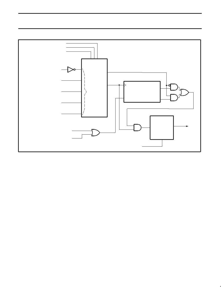
CLOCK SELECT
CLOCK
SOURCES
CLOCK
OUT
XTAL
SELECT
INTERNAL RC OSCILLATOR
CRYSTAL: LOW FREQUENCY
CRYSTAL: MEDIUM FREQUENCY
CRYSTAL: HIGH FREQUENCY
EXTERNAL CLOCK INPUT
10-BIT RIPPLE COUNTER
RESET
COUNT
COUNT 256
COUNT 1024
OSCILLATOR STARTUP TIMER
DIVIDE-BY-M
(DIVM REGISTER)
AND
CLKR SELECT
CPU
CLOCK
÷1/÷2
CLKR
(UCFG1.3)
POWER DOWN
POWER MONITOR RESET
FOSC0 (UCFG1.0)
FOSC1 (UCFG1.1)
FOSC2 (UCFG1.2)
Figure 20. Block Diagram of Oscillator Control
CPU Clock Modification: CLKR and DIVM
For backward compatibility, the CLKR configuration bit allows
setting the P87LPC767 instruction and peripheral timing to match
standard 80C51 timing by dividing the CPU clock by two. Default
timing for the P87LPC767 is 6 CPU clocks per machine cycle while
standard 80C51 timing is 12 clocks per machine cycle. This
division also applies to peripheral timing, allowing 80C51 code that
is oscillator frequency and/or timer rate dependent. The CLKR bit
is located in the EPROM configuration register UCFG1, described
under EPROM Characteristics
In addition to this, the CPU clock may be divided down from the
oscillator rate by a programmable divider, under program control.
This function is controlled by the DIVM register. If the DIVM register
is set to zero (the default value), the CPU will be clocked by either
the unmodified oscillator rate, or that rate divided by two, as
determined by the previously described CLKR function.
When the DIVM register is set to some value N (between 1 and 255),
the CPU clock is divided by 2 * (N + 1). Clock division values from 4
through 512 are thus possible. This feature makes it possible to
temporarily run the CPU at a lower rate, reducing power consumption,
in a manner similar to Idle mode. By dividing the clock, the CPU can
retain the ability to respond to events other than those that can cause
interrupts (i.e., events that allow exiting the Idle mode) by executing
its normal program at a lower rate. This can allow bypassing the
oscillator startup time in cases where Power Down mode would
otherwise be used. The value of DIVM may be changed by the
program at any time without interrupting code execution.
Power Monitoring Functions
The P87LPC767 incorporates power monitoring functions designed
to prevent incorrect operation during initial power up and power loss
or reduction during operation. This is accomplished with two
hardware functions: Power-On Detect and Brownout Detect.
Brownout Detection
The Brownout Detect function allows preventing the processor from
failing in an unpredictable manner if the power supply voltage drops
below a certain level. The default operation is for a brownout
detection to cause a processor reset, however it may alternatively
be configured to generate an interrupt by setting the BOI bit in the
AUXR1 register (AUXR1.5).
The P87LPC767 allows selection of two Brownout levels: 2.5 V or
3.8 V. When VDD drops below the selected voltage, the brownout
detector triggers and remains active until VDD is returns to a level
above the Brownout Detect voltage. When Brownout Detect causes
a processor reset, that reset remains active as long as VDD remains
below the Brownout Detect voltage. When Brownout Detect
generates an interrupt, that interrupt occurs once as VDD crosses
from above to below the Brownout Detect voltage. For the interrupt
to be processed, the interrupt system and the BOI interrupt must
both be enabled (via the EA and EBO bits in IEN0).
When Brownout Detect is activated, the BOF flag in the PCON
register is set so that the cause of processor reset may be determined
by software. This flag will remain set until cleared by software.
相关PDF资料 |
PDF描述 |
|---|---|
| PIC18F45J10-I/P | IC PIC MCU FLASH 16KX16 40DIP |
| PIC24FJ16GA002-I/SO | IC PIC MCU FLASH 16K 28-SOIC |
| PIC18F25K22-I/SO | MCU 8BIT 32KB FLASH 5.5V 28SOIC |
| PIC18F26K20-I/SS | IC PIC MCU FLASH 32KX16 28-SSOP |
| PIC24F08KA102-I/ML | IC PIC MCU FLASH 8K 28-QFN |
相关代理商/技术参数 |
参数描述 |
|---|---|
| PIC18F85J90-I/PT | 功能描述:8位微控制器 -MCU 32KB Flash 2048BRAM 67I/O RoHS:否 制造商:Silicon Labs 核心:8051 处理器系列:C8051F39x 数据总线宽度:8 bit 最大时钟频率:50 MHz 程序存储器大小:16 KB 数据 RAM 大小:1 KB 片上 ADC:Yes 工作电源电压:1.8 V to 3.6 V 工作温度范围:- 40 C to + 105 C 封装 / 箱体:QFN-20 安装风格:SMD/SMT |
| PIC18F85J90T-I/PT | 功能描述:8位微控制器 -MCU 32KB Flash 2048bytes-RAM 67I/O RoHS:否 制造商:Silicon Labs 核心:8051 处理器系列:C8051F39x 数据总线宽度:8 bit 最大时钟频率:50 MHz 程序存储器大小:16 KB 数据 RAM 大小:1 KB 片上 ADC:Yes 工作电源电压:1.8 V to 3.6 V 工作温度范围:- 40 C to + 105 C 封装 / 箱体:QFN-20 安装风格:SMD/SMT |
| PIC18F85J94-I/PT | 制造商:Microchip Technology Inc 功能描述:80 PINS, 32KB FLASH, 4KB RAM, 16MIPS, NANOWATT XLP, LCD, USB - Trays |
| PIC18F85J94T-I/PT | 制造商:Microchip Technology Inc 功能描述:80 PINS, 32KB FLASH, 4KB RAM, 16MIPS, NANOWATT XLP, LCD, USB - Tape and Reel 制造商:Microchip Technology Inc 功能描述:IC MCU 8BIT 32KB FLASH 80TQFP 制造商:Microchip Technology Inc 功能描述:8-bit Microcontrollers - MCU 80 pins, 32KB Flash, 4KB RAM, 16MIPS 制造商:Microchip Technology Inc 功能描述:80 pins, 32KB Flash, 4KB RAM, 16MIPS, nanoWatt XLP, LCD, USB, 80 TQFP 12x12x1mm |
| PIC18F85K22-E/PT | 功能描述:8位微控制器 -MCU 32KB Flash 2KB RAM RoHS:否 制造商:Silicon Labs 核心:8051 处理器系列:C8051F39x 数据总线宽度:8 bit 最大时钟频率:50 MHz 程序存储器大小:16 KB 数据 RAM 大小:1 KB 片上 ADC:Yes 工作电源电压:1.8 V to 3.6 V 工作温度范围:- 40 C to + 105 C 封装 / 箱体:QFN-20 安装风格:SMD/SMT |
发布紧急采购,3分钟左右您将得到回复。