- 您现在的位置:买卖IC网 > PDF目录98071 > S82451KX (INTEL CORP) SPECIALTY MICROPROCESSOR CIRCUIT, PQFP144 PDF资料下载
参数资料
| 型号: | S82451KX |
| 厂商: | INTEL CORP |
| 元件分类: | 微控制器/微处理器 |
| 英文描述: | SPECIALTY MICROPROCESSOR CIRCUIT, PQFP144 |
| 封装: | QFP-144 |
| 文件页数: | 7/180页 |
| 文件大小: | 1094K |
| 代理商: | S82451KX |
第1页第2页第3页第4页第5页第6页当前第7页第8页第9页第10页第11页第12页第13页第14页第15页第16页第17页第18页第19页第20页第21页第22页第23页第24页第25页第26页第27页第28页第29页第30页第31页第32页第33页第34页第35页第36页第37页第38页第39页第40页第41页第42页第43页第44页第45页第46页第47页第48页第49页第50页第51页第52页第53页第54页第55页第56页第57页第58页第59页第60页第61页第62页第63页第64页第65页第66页第67页第68页第69页第70页第71页第72页第73页第74页第75页第76页第77页第78页第79页第80页第81页第82页第83页第84页第85页第86页第87页第88页第89页第90页第91页第92页第93页第94页第95页第96页第97页第98页第99页第100页第101页第102页第103页第104页第105页第106页第107页第108页第109页第110页第111页第112页第113页第114页第115页第116页第117页第118页第119页第120页第121页第122页第123页第124页第125页第126页第127页第128页第129页第130页第131页第132页第133页第134页第135页第136页第137页第138页第139页第140页第141页第142页第143页第144页第145页第146页第147页第148页第149页第150页第151页第152页第153页第154页第155页第156页第157页第158页第159页第160页第161页第162页第163页第164页第165页第166页第167页第168页第169页第170页第171页第172页第173页第174页第175页第176页第177页第178页第179页第180页
96
PRELIMINARY
82453KX/GX, 82452KX/GX, 82451KX/GX (MC)
A
1.2
DP Signals
.
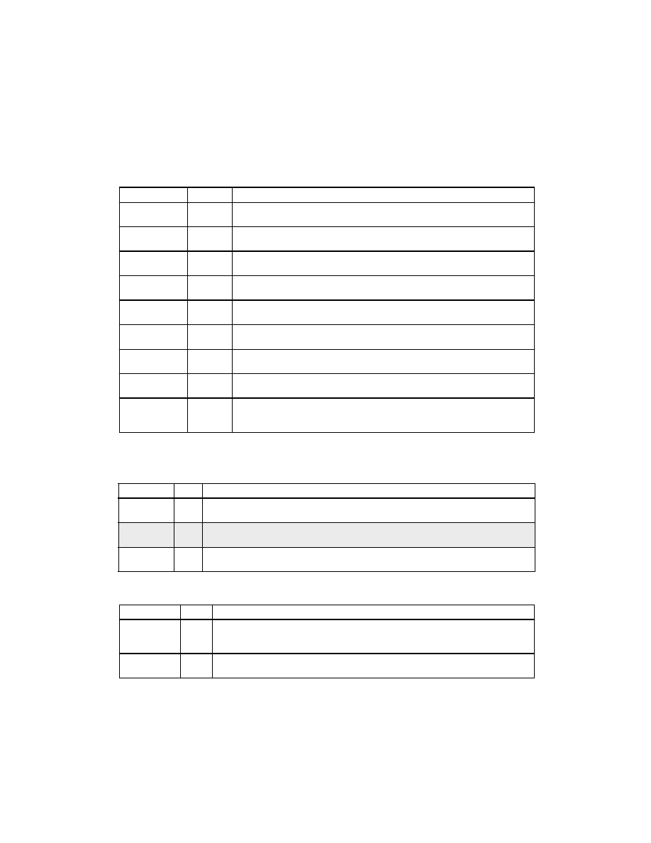
Table 7. Test Signals (DC)
Signal
Type
Description
GTLHI
I/O
GTL+
These signals must be tied to VTT using a 10K resistor for proper operation in
both test and normal operating modes.
TCK
I
CMOS
JTAG Test Clock. When TMS is tied low, this signal has no effect on normal
operation.
TDI
I
CMOS
JTAG Test Data In. When TMS is tied low, this signal has no effect on normal
operation.
TDO
O
CMOS
JTAG Test Data Out. When TMS is tied low, this signal has no effect on normal
operation.
TESTHI
I/O
TEST HIGH. These signals must be tied high using a 10K
resistor for proper
operation in both test and normal operating modes.
TESTLO
I/O
TEST LOW. These signals must be tied low using a 1K
resistor for proper
operation in both test and normal operating modes.
TMS
I
CMOS
JTAG Test Mode Select. This signal must be tied low for normal operation.
TRST#
I
CMOS
JTAG Test Reset. When TMS is tied low, this signal has no effect on normal
operation.
RECVEN
I
RECEIVER ENABLE. This function is useful for component test. This signal is
negated with PWRGOOD to disable GTL+ receivers and tri-state outputs for
board test.
Table 8. Host Bus Interface Signals (DP)
Signal
Type
Description
D[63:0]#
I/O
GTL+
DATA BUS. The data bus consists of eight bytes.
DEP[7:0]#
I/O
GTL+
DATA ECC/PARITY. DEP[7:0]# provides ECC for the D[63:0]# signals. ECC is
computed over the 64 data bits. Parity is not generated or checked by the MC.
DRDY#
I/O
GTL+
DATA READY. Asserted for each cycle that data is transferred.
Table 9. Data Path Interface Signals (DP)
Signal
Type
Description
MDE[71:0]
I/O
CMOS
MEMORY DATA AND ECC. Common to all types and sizes of memory supported,
these signals include the 64 bits of data and 8 ECC check bits. ECC is computed
over 64-bit data words. Parity is computed as byte-parity over a 64-bit word.
MDRDY0#
MDRDY1#
O
CMOS
MEMORY DATA READY (TWO COPIES). Asserted when write data on the MDE
bus is valid. Two copies are provided to support external loading.
相关PDF资料 |
PDF描述 |
|---|---|
| S83296SA | 16-BIT, MROM, 40 MHz, MICROCONTROLLER, PQFP100 |
| SB83296SA | 16-BIT, MROM, 40 MHz, MICROCONTROLLER, PQFP100 |
| S83C196MH | 16-BIT, MROM, 16 MHz, MICROCONTROLLER, PQFP80 |
| S83C51FB-BB44 | 8-BIT, MROM, 24 MHz, MICROCONTROLLER, PQFP44 |
| S83C51FC-5B44 | 8-BIT, MROM, 16 MHz, MICROCONTROLLER, PQFP44 |
相关代理商/技术参数 |
参数描述 |
|---|---|
| S82452KX | 制造商:未知厂家 制造商全称:未知厂家 功能描述:Data Path Controller |
| S82453KX | 制造商:未知厂家 制造商全称:未知厂家 功能描述:DRAM Controller |
| S82454KX | 制造商:未知厂家 制造商全称:未知厂家 功能描述:PCI Bus Interface/Controller |
| S8248P12NF | 功能描述:ANTENNA 824-896MHZ 8DBI N FML RoHS:是 类别:RF/IF 和 RFID >> RF 天线 系列:* 标准包装:1 系列:* |
| S82510 DIE | 制造商:Intel 功能描述: |
发布紧急采购,3分钟左右您将得到回复。