参数资料
| 型号: | SAA7706H/N210,518 |
| 厂商: | NXP Semiconductors |
| 文件页数: | 14/52页 |
| 文件大小: | 0K |
| 描述: | IC CAR RADIO DSP 80-QFP |
| 标准包装: | 500 |
| 类型: | 汽车信号处理器 |
| 接口: | I²C,I²:S,LSB,SPDIF |
| 电压 - 输入/输出: | 3.30V |
| 电压 - 核心: | 3.30V |
| 工作温度: | -40°C ~ 85°C |
| 安装类型: | 表面贴装 |
| 封装/外壳: | 80-BQFP |
| 供应商设备封装: | 80-QFP(14x20) |
| 包装: | 带卷 (TR) |
| 其它名称: | 935270285518 SAA7706H/N210-T SAA7706H/N210-T-ND |
第1页第2页第3页第4页第5页第6页第7页第8页第9页第10页第11页第12页第13页当前第14页第15页第16页第17页第18页第19页第20页第21页第22页第23页第24页第25页第26页第27页第28页第29页第30页第31页第32页第33页第34页第35页第36页第37页第38页第39页第40页第41页第42页第43页第44页第45页第46页第47页第48页第49页第50页第51页第52页
2001 Mar 05
21
Philips Semiconductors
Product specication
Car radio Digital Signal Processor (DSP)
SAA7706H
8.5
DCS clock
In radio mode the stereo decoder, the ADC3 and RDS
demodulator, the ADC1 or ADC2 and the level decimation
filters have to run synchronously to the 19 kHz pilot.
Therefore a clock signal with a controlled frequency of a
multiple of 19 kHz (9.728 MHz = 512
× 19 kHz) is needed.
In the SAA7706H the patented method of non-equidistant
digitally controlled sampling DCS clock has been
implemented. By a special dividing mechanism a
frequency of 9.728 MHz from the PLL2 clock frequency of
>40 MHz is generated. The dividing can be changed by
means of I2C-bus bits to cope with the different input
frequencies of the DCS block.
The DCS system is controlled by up or down information
from the stereo decoder. In the event of mono
transmissions or 44.1 kHz ADC1 or ADC2 usage the DCS
clock is still controlled by the stereo decoder loop. The
output keeps the DCS free running on a multiple frequency
of 19 kHz
±2 Hz if the correct clock setting is applied. In
tape/cd of either 38 or 44.1 kHz and AM mode the DCS
clock always has to be put in preset mode with a bit in the
I2C-bus memory map definitions.
8.6
The Interference Absorption Circuit (IAC)
8.6.1
GENERAL DESCRIPTION
The IAC detects and suppresses ignition interference. This
hardware IAC is a modified, digitized and extended
version of the analog circuit which is in use for many years
already.
The IAC consists of an MPX mute function switched by
mute pulses from ignition interference pulse detectors.
The input signal of a second IAC detection circuit is the
FM level signal (the output of the level-ADC). This detector
performs optimally in lower antenna voltage
circumstances. It is therefore complementary to the first
detector.
The input signal of a first IAC detection circuit is the output
signal of one of the down-sample paths coming from ADC1
or ADC2. This interference detector analyses the
high-frequency contents of the MPX signal. The
discrimination between interference pulses and other
signals is performed by a special Philips patented fuzzy
logic such as algorithm and is based on probability
calculations. This detector performs optimally in higher
antenna voltage circumstances. On detection of ignition
interference, this logic will send appropriate pulses to the
MPX mute switch.
The characteristics of both IAC detectors can be adapted
to the properties of different FM front-ends by means of the
predefined coefficients in the IAC control registers. The
values can be changed via the I2C-bus. Both IAC detectors
can be switched on or off independently of each other.
Both IAC detectors can mute the MPX signal
independently of each other.
A third IAC function is the dynamic IAC circuit. This block
is intended to switch off the IAC completely the moment
the MPX signal has a too high frequency deviation which
in the event of small IF filters can result in AM modulation.
This AM modulation could be interpreted by the IAC
circuitry as interference caused by the car’s engine.
8.7
The Filter Stream DAC (FSDAC)
The FSDAC is a semi-digital reconstruction filter that
converts the 1-bit data stream of the noise shaper to an
analog output voltage. The filter coefficients are
implemented as current sources and are summed at
virtual ground of the output operational amplifier. In this
way very high signal-to-noise performance and low clock
jitter sensitivity is achieved. A post-filter is not needed due
to the inherent filter function of the DAC. On-board
amplifiers convert the FSDAC output current to an output
voltage signal capable of driving a line output.
The output voltage of the FSDAC scales proportionally
with the power supply voltage.
8.7.1
INTERPOLATION FILTER
The digital filter interpolates from 1 to 64fs by means of a
cascade of a recursive filter and an FIR filter.
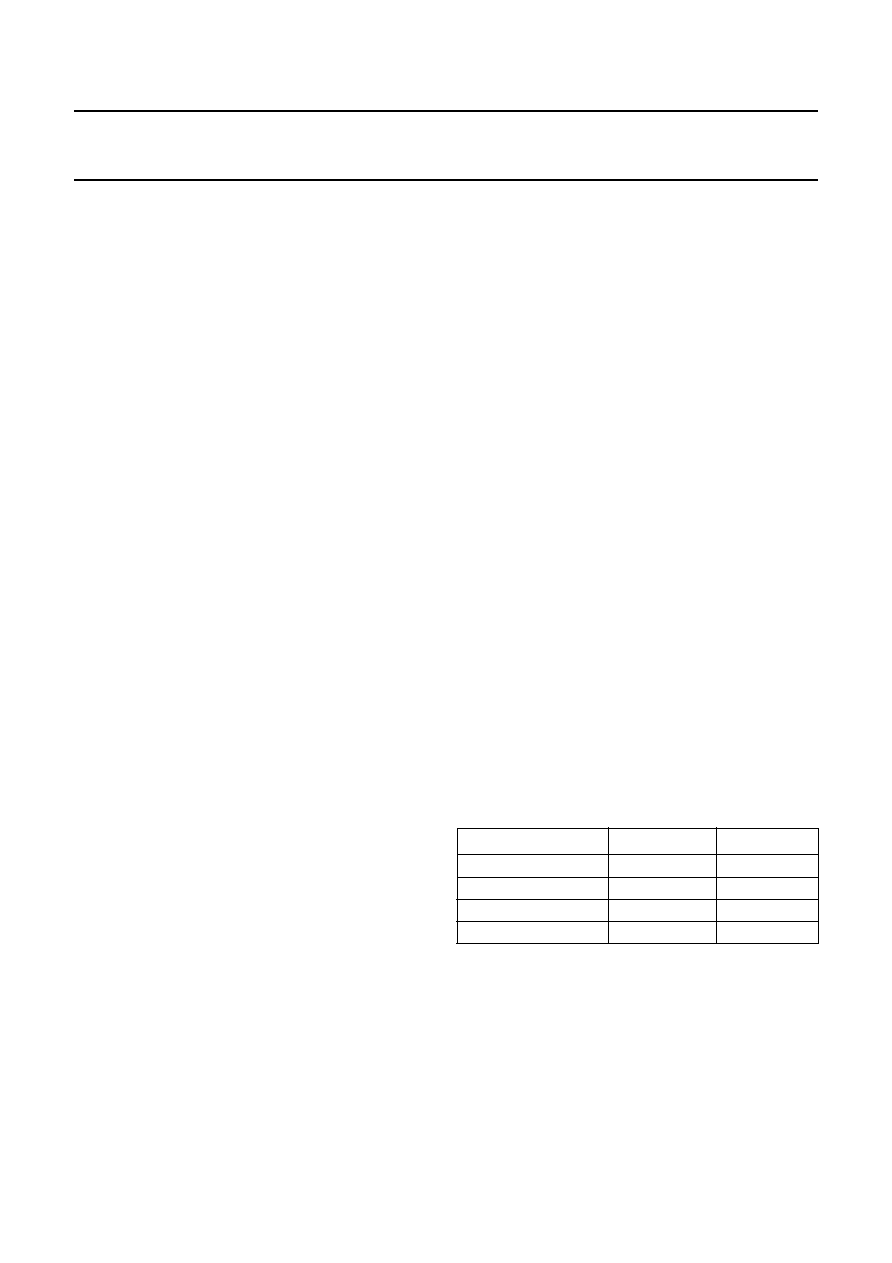
Table 2
Digital interpolation lter characteristics
8.7.2
NOISE SHAPER
The 5th-order noise shaper operates at 64fs. It shifts
in-band quantization noise to frequencies well above the
audio band. This noise shaping technique enables high
signal-to-noise ratios to be achieved. The noise shaper
output is converted into an analog signal using a filter
stream digital-to-analog converter.
ITEM
CONDITIONS
VALUE (dB)
Pass band ripple
0
0.45f
s
±0.03
Stop band
>0.55fs
50
Dynamic range
0
0.45f
s
116.5
Gain
DC
3.5
相关PDF资料 |
PDF描述 |
|---|---|
| SAB-C161O-LM HA | IC MICROCONTROLLER 16BIT 80-MQFP |
| SAB-C165-LM 3V HA | IC MCU 16BIT MQFP-100-2 |
| SAF-C161S-L25M AA | IC MCU 16BIT ROM/LESS MQFP-80-7 |
| SAK-XC2237M-104F40L | IC MCU 16BIT 320KB FLASH 64LQFP |
| SAK-XC2365B-40F80L | IC MCU 16BIT FLASH 100-LQFP |
相关代理商/技术参数 |
参数描述 |
|---|---|
| SAA7707H | 制造商:PHILIPS 制造商全称:NXP Semiconductors 功能描述:Car radio Digital Signal Processor CDSP |
| SAA7708H | 制造商:PHILIPS 制造商全称:NXP Semiconductors 功能描述:Car Radio Digital Signal Processor |
| SAA7709/N107 | 制造商:PHILIPS-SEMI 功能描述: |
| SAA7709H/N103 | 功能描述:音频 DSP DIGITAL SIGNAL PROCESSOR RoHS:否 制造商:Texas Instruments 工作电源电压: 电源电流: 工作温度范围: 安装风格: 封装 / 箱体: 封装:Tube |
| SAA7709H/N103,518 | 功能描述:音频 DSP DIRAC-2 RoHS:否 制造商:Texas Instruments 工作电源电压: 电源电流: 工作温度范围: 安装风格: 封装 / 箱体: 封装:Tube |
发布紧急采购,3分钟左右您将得到回复。