- 您现在的位置:买卖IC网 > PDF目录297406 > SL811HS (CYPRESS SEMICONDUCTOR CORP) SL811HS Embedded USB Host/Slave Controller(SL811HS嵌入式USB主/从控制器) PDF资料下载
参数资料
| 型号: | SL811HS |
| 厂商: | CYPRESS SEMICONDUCTOR CORP |
| 元件分类: | 总线控制器 |
| 英文描述: | SL811HS Embedded USB Host/Slave Controller(SL811HS嵌入式USB主/从控制器) |
| 中文描述: | UNIVERSAL SERIAL BUS CONTROLLER, PQCC28 |
| 封装: | PLASTIC, LCC-28 |
| 文件页数: | 6/32页 |
| 文件大小: | 455K |
| 代理商: | SL811HS |
第1页第2页第3页第4页第5页当前第6页第7页第8页第9页第10页第11页第12页第13页第14页第15页第16页第17页第18页第19页第20页第21页第22页第23页第24页第25页第26页第27页第28页第29页第30页第31页第32页
SL811HS
Document 38-08008 Rev. *B
Page 14 of 32
3.2.3.5
Endpoint Transfer Count [Address a = (EP# * 10h)+4, b = (EP# * 10h)+Ch]
As a peripheral device, the Endpoint Transfer Count register is only important with OUT tokens (host sending the slave data).
When a host sends the peripheral data, the Transfer Count register will contain the difference between the Endpoint Base Length
and the actual number of bytes received in the last packet. In other words if the Endpoint Base Length register was set for 64
(40h) bytes and an OUT token was sent to the endpoint that only had 16 (10h) bytes, the Endpoint Transfer Count register would
have a value of 48 (30h). If more bytes were sent in an OUT token then the Endpoint Base Length register was programmed for
the overflow flag will be set in the Endpoint Packet Status register and is considered a serious error.
3.2.4
USB Control Registers
The USB Control registers manage communication and data flow on the USB. Each USB device is composed of a collection of
independently operating endpoints. Each endpoint has a unique identifier, which is the Endpoint Number. For more details about
USB endpoints, please refer to the USB Specification 1.1, Section 5.3.1.
The control and status registers are mapped as follows:
3.2.4.1
Control Register 1, Address [05h]
The Control Register enables or disables USB transfers and DMA Operations with control bits.
3
Sequence
The Sequence bit indicates if the last packet was a DATA0 (0) or DATA1 (1).
2
Time-out
This bit is not used in slave mode.
1
Error
Error detected in transmission, this includes CRC5/16 and PID errors.
0
ACK
Transmission Acknowledge.
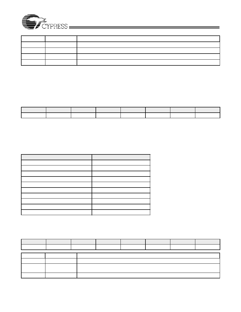
Table 3-26. Endpoint Transfer Count Reg [Address EP0a/b:04h/0Ch, EP1a/b:14h/1Ch, EP2a/b:24h/2Ch, EP3a/b:34h/3Ch]
7
6
5
4
3
2
1
0
EPxCNT7
EPxCNT6
EPxCNT5
EPxCNT4
EPxCNT3
EPxCNT2
EPxCNT1
EPxCNT0
Bit Position Bit Name
Function
Table 3-27. Control and Status Register Map
Register Name
Address (in Hex)
Control Register 1
05h
Interrupt Enable Register
06h
USB Address Register
07h
Interrupt Status Register
0Dh
Current Data Set Register
0Eh
Control Register 2
0Fh
SOF Low Byte Register
15h
SOF High Byte Register
16h
DMA Total Count Low Byte Register
35h
DMA Total Count High Byte Register
36h
Table 3-28. Control Register 1 [Address 05h]
7
6
5
4
3
2
1
0
Reserved
STBYD
SPSEL
J-K1
J-K0
DMA Dir
DMA Enable
USB Enable
Bit Position Bit Name
Function
7
Reserved
Reserved bit - must be set to '0'.
6
STBYD
XCVR Power control. 1 sets XCVR to low power. For normal operation set this bit = 0.
Suspend mode is entered if Bit 6 = 1 and Bit 0 (USB Enable) = 0.
5
SPSEL
Speed Select. 0 selects Full-Speed. 1 selects Low-Speed (also see Table 3-34)
相关PDF资料 |
PDF描述 |
|---|---|
| SLA0201 | 600 V, SCR |
| SLA24C01-D-3/P | The CAT24FC02 is a 2-kb Serial CMOS EEPROM internally organized as 256 words of 8 bits each |
| SLA24C01-D/P | The CAT24FC02 is a 2-kb Serial CMOS EEPROM internally organized as 256 words of 8 bits each |
| SLE24C01-S/P | The CAT24FC02 is a 2-kb Serial CMOS EEPROM internally organized as 256 words of 8 bits each |
| SLE24C02-D/P | The CAT24FC02 is a 2-kb Serial CMOS EEPROM internally organized as 256 words of 8 bits each |
相关代理商/技术参数 |
参数描述 |
|---|---|
| SL811HS_07 | 制造商:CYPRESS 制造商全称:Cypress Semiconductor 功能描述:Embedded USB Host/Slave Controller |
| SL811HS_11 | 制造商:CYPRESS 制造商全称:Cypress Semiconductor 功能描述:Embedded USB Host/Slave Controller |
| SL811HS-DK | 制造商:Cypress Semiconductor 功能描述:Embedded USB Host/Slave Controller 28-Pin PLCC |
| SL811HS-JCT | 制造商:Cypress Semiconductor 功能描述: |
| SL811HST | 制造商:CYPRESS 制造商全称:Cypress Semiconductor 功能描述:Embedded USB Host/Slave Controller |
发布紧急采购,3分钟左右您将得到回复。