- 您现在的位置:买卖IC网 > PDF目录69366 > ST72622L2T1 (STMICROELECTRONICS) 8-BIT, MROM, 8 MHz, MICROCONTROLLER, PQFP44 PDF资料下载
参数资料
| 型号: | ST72622L2T1 |
| 厂商: | STMICROELECTRONICS |
| 元件分类: | 微控制器/微处理器 |
| 英文描述: | 8-BIT, MROM, 8 MHz, MICROCONTROLLER, PQFP44 |
| 封装: | TQFP-44 |
| 文件页数: | 44/134页 |
| 文件大小: | 815K |
| 代理商: | ST72622L2T1 |
第1页第2页第3页第4页第5页第6页第7页第8页第9页第10页第11页第12页第13页第14页第15页第16页第17页第18页第19页第20页第21页第22页第23页第24页第25页第26页第27页第28页第29页第30页第31页第32页第33页第34页第35页第36页第37页第38页第39页第40页第41页第42页第43页当前第44页第45页第46页第47页第48页第49页第50页第51页第52页第53页第54页第55页第56页第57页第58页第59页第60页第61页第62页第63页第64页第65页第66页第67页第68页第69页第70页第71页第72页第73页第74页第75页第76页第77页第78页第79页第80页第81页第82页第83页第84页第85页第86页第87页第88页第89页第90页第91页第92页第93页第94页第95页第96页第97页第98页第99页第100页第101页第102页第103页第104页第105页第106页第107页第108页第109页第110页第111页第112页第113页第114页第115页第116页第117页第118页第119页第120页第121页第122页第123页第124页第125页第126页第127页第128页第129页第130页第131页第132页第133页第134页
ST7262
17/134
FLASH PROGRAM MEMORY (Cont’d)
4.5 ICP (In-Circuit Programming)
To perform ICP the microcontroller must be
switched to ICC (In-Circuit Communication) mode
by an external controller or programming tool.
Depending on the ICP code downloaded in RAM,
Flash memory programming can be fully custom-
ized (number of bytes to program, program loca-
tions, or selection serial communication interface
for downloading).
When using an STMicroelectronics or third-party
programming tool that supports ICP and the spe-
cific microcontroller device, the user needs only to
implement the ICP hardware interface on the ap-
plication board (see Figure 2). For more details on
the pin locations, refer to the device pinout de-
scription.
ICP needs five signals to be connected to the pro-
gramming tool. These signals are:
– RESET: device reset
–VSS: device power supply ground
– ICCCLK: ICC output serial clock pin
– ICCDATA: ICC input serial data pin
–VPP: programming voltage
When the device is not yet configured to support
the application clock source (option byte not yet
programmed) or if the option bytes have to be pro-
grammed using ICP, one more pin has to be con-
nected:
– OSCIN: main clock input for external source
When the device is not supplied (VDD) by the ap-
plication, one more pin has to be connected:
–VDD: main power supply
CAUTIONS:
1. If RESET, ICCCLK or ICCDATA pins are used
for other purposes in the application, a serial resis-
tor has to be implemented to avoid a conflict in
case one of the other devices forces the signal lev-
el.
2. As soon as the external controller is plugged to
the board, even if an ICC session is not in
progress, the ICCCLK and ICCDATA pins are not
available for the application.
Note: To develop a custom programming tool, re-
fer to the ST7 Flash Programming and ICC Refer-
ence Manual which gives full details on the ICC
protocol hardware and software.
4.6 IAP (In-Application Programming)
This mode uses a BootLoader program previously
stored in Sector 0 by the user (in ICP mode or by
plugging the device in a programming tool).
This mode is fully controlled by user software. This
allows it to be adapted to the user application, (us-
er-defined strategy for entering programming
mode, choice of communications protocol used to
fetch the data to be stored, etc.). For example, it is
possible to download code from the SPI, SCI, USB
or CAN interface and program it in the Flash. IAP
mode can be used to program any of the Flash
sectors except Sector 0, which is write/erase pro-
tected to allow recovery in case errors occur dur-
ing the programming operation.
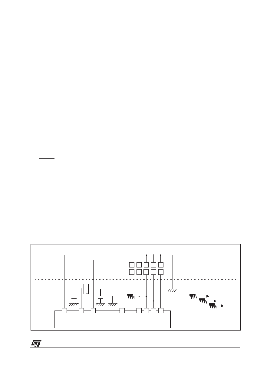
Figure 9. Typical ICP Interface
ICP PROGRAMMING TOOL CONNECTOR
10k
CL2
CL1
1
ICCDATA
ICCCLK
RESET
VSS
VDD
VPP
OSCIN
OSCOUT
ST7
HE10 CONNECTOR TYPE
APPLICATI ON
4.7k
TO
T
H
EA
PPL
IC
AT
ION
BOARD
1
相关PDF资料 |
PDF描述 |
|---|---|
| ST72621L4T1 | 8-BIT, MROM, 8 MHz, MICROCONTROLLER, PQFP44 |
| ST72632K2B1/XXX | 8-BIT, MROM, 8 MHz, MICROCONTROLLER, PDIP32 |
| ST72E631K4D0 | 8-BIT, UVPROM, 8 MHz, MICROCONTROLLER, PDIP32 |
| ST72633K1M1/XXX | 8-BIT, MROM, 8 MHz, MICROCONTROLLER, PDSO34 |
| ST7263BK1M1/XXX | 8-BIT, MROM, 8 MHz, MICROCONTROLLER, PDSO34 |
相关代理商/技术参数 |
参数描述 |
|---|---|
| ST7263-EMU2 | 功能描述:仿真器/模拟器 ST7 Emulator Board RoHS:否 制造商:Blackhawk 产品:System Trace Emulators 工具用于评估:C6000, C5000, C2000, OMAP, DAVINCI, SITARA, TMS470, TMS570, ARM 7/9, ARM Cortex A8/R4/M3 用于:XDS560v2 |
| ST7265X-EVAL/MS | 制造商:STMicroelectronics 功能描述:ST6 EVAL BD - Bulk |
| ST7265X-EVAL/PFD | 制造商:STMicroelectronics 功能描述:USB FLASH EVAL - Bulk |
| ST7266 | 制造商:6940 功能描述:ST7266 |
| ST7267C8T1L | 制造商:STMicroelectronics 功能描述: |
发布紧急采购,3分钟左右您将得到回复。