- 您现在的位置:买卖IC网 > PDF目录69381 > STEL-1175+125/CM (INTEL CORP) 8-BIT, DSP-NUM CONTROLLED OSCILLATOR, PQCC68 PDF资料下载
参数资料
| 型号: | STEL-1175+125/CM |
| 厂商: | INTEL CORP |
| 元件分类: | 数字信号处理外设 |
| 英文描述: | 8-BIT, DSP-NUM CONTROLLED OSCILLATOR, PQCC68 |
| 封装: | PLASTIC, LCC-68 |
| 文件页数: | 10/14页 |
| 文件大小: | 253K |
| 代理商: | STEL-1175+125/CM |
5
STEL-1175+125
clock edges, and thereafter will remain at the value
corresponding to zero phase (801H) until new frequency
or phase modulation data is loaded with the FRLD or
PHLD inputs after the RESET returns high.
CLOCK
All synchronous functions performed within the NCO are
referenced to the rising edge of the CLOCK input. The
CLOCK signal should be nominally a square wave at a
maximum frequency of 125 MHz. A non-repetitive
CLOCK waveform is permissible as long as the minimum
duration positive or negative pulse on the waveform is
always greater than 4 nanoseconds.
CSEL
The Chip Select input is used to control the writing of
data into the chip. It is active low. When this input is high
all data writing via the DATA7-0 bus is inhibited.
DATA7 through DATA0
The 8-bit DATA7-0 bus is used to program the two 32-bit
-Phase Registers and the 12-bit Phase Modulation
Register. DATA0 is the least significant bit of the bus. The
data programmed into the -Phase registers in this way
determines the output frequency of the NCO.
ADDR3 through ADDR0
The four address lines ADDR3-0 control the use of the
DATA7-0 bus for writing frequency data to the -Phase
Buffer Registers, and phase data to the Phase Buffer
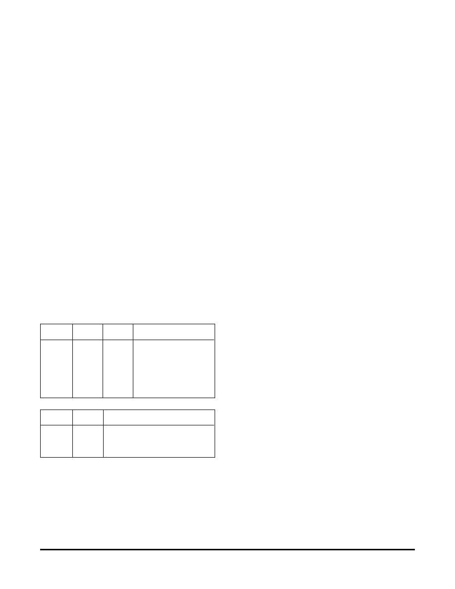
Register, as shown in the tables:
ADDR3 ADDR1 ADDR0 Register Field
00
0
-Phase Bits 7 0(LSB)
00
1
-Phase Bits15 8
01
0
-Phase Bits 23 16
01
1
-Phase Bits 31 24
1
0
Phase Bits 3* 0(LSB)
1
0
1
Phase Bits 11* 4
ADDR3 ADDR2
Register Selected
00
-Phase Buffer Register 'A'
01
-Phase Buffer Register 'B'
1
X
Phase Buffer Register
* Note: The Phase Buffer Register is a 12-bit register.
When the least significant byte of this register is selected
(ADDR3-0 =1X00), DATA7-4 is written into Bits 30 of
the register. In all cases, it is not necessary to reload
unchanged bytes, and the byte loading sequence may be
random.
WRSTB
The Write Strobe input is used to latch the data on the
DATA7-0 bus into the device. On the rising edge of the
WRSTB input, the information on the 8-bit data
bus is transferred to the buffer register selected by the
ADDR3-0bus.
FRSEL
The Frequency Register Select line controls the mux
which selects the -Phase Buffer Register in use. When
this signal is high -Phase Buffer Register 'A' is selected as
the source for the -Phase Register, and the frequency
corresponding to the data stored in this register will be
generated by the NCO after the next FRLD command.
When this line is low, -Phase Buffer Register 'B' is
selected as the source.
FRLD
The Frequency Load input is used to control the transfer
of the data from the -Phase Buffer Registers to the -
Phase Register. The data at the output of the Mux Block
must be valid during the clock cycle following the falling
edge of FRLD. The data is then transferred during the
subsequent cycle. The frequency of the NCO output will
change 19 rising clock edges after the FRLD command
due to pipelining delays.
PHSEL
The Phase Source Select input selects the source of data
for the Phase ALU. When it is high the source is the Phase
Buffer Register. It is loaded from the
DATA7-
0 bus by setting address line ADDR3 high, as shown in the
tables. When PHSEL is low, the sources for the phase
modulation data are the DATA7-0 and ADDR3-0 inputs,
and the data will be loaded independently of the states of
WRSTB and CSEL. The data on these 12 inputs is
presented directly as a parallel 12-bit word to the Phase
ALU, allowing high-speed phase modulation. The 12-bit
value is latched into the Phase ALU by means of the PHLD
input. The data on the ADDR3-0lines is mapped onto Phase
Bits 3 to 0 and the data on the DATA7-0 lines are mapped
onto Phase Bits 11 to 4 in this case. When using the parallel
phase load mode CSEL and/or WRSTB should remain
high to ensure that the phase data is not written into the
phase and frequency buffer registers of the STEL-1175.
PHLD
The Phase Load input is used to control the latching of
the Phase Modulation data into the Phase ALU. The 12-
bit data at the output of the Phase Modulation Control
Block must be valid during the clock cycle following the
falling edge of PHLD. The data is then transferred during
the subsequent cycle. The 12-bit phase data is added to the
12 most significant bits of the accumulator output, so that
the MSB of the phase data represents a 180° phase change.
The source of this data will be determined by the state of
相关PDF资料 |
PDF描述 |
|---|---|
| STEL-1175+125/MC | 8-BIT, DSP-NUM CONTROLLED OSCILLATOR, CQCC68 |
| STEL-1177/CF | 8-BIT, DSP-NUM CONTROLLED OSCILLATOR, CPGA84 |
| STG2000XC | SPECIALTY MICROPROCESSOR CIRCUIT, PQFP208 |
| STK17C88-W45 | REAL TIME CLOCK, PDIP40 |
| STK17T88-R25I | REAL TIME CLOCK, PDSO48 |
相关代理商/技术参数 |
参数描述 |
|---|---|
| STEL-1176/CM | 制造商:未知厂家 制造商全称:未知厂家 功能描述:Numeric-Controlled Oscillator |
| STEL-1176/MC | 制造商:未知厂家 制造商全称:未知厂家 功能描述:Numeric-Controlled Oscillator |
| STEL-1177/CC | 制造商:未知厂家 制造商全称:未知厂家 功能描述:Numeric-Controlled Oscillator |
| STEL-1177/CF | 制造商:未知厂家 制造商全称:未知厂家 功能描述:Numeric-Controlled Oscillator |
| STEL-1177/CM | 制造商:未知厂家 制造商全称:未知厂家 功能描述:Numeric-Controlled Oscillator |
发布紧急采购,3分钟左右您将得到回复。