- 您现在的位置:买卖IC网 > PDF目录98152 > TA1310ANG SPECIALTY CONSUMER CIRCUIT, PDIP56 PDF资料下载
参数资料
| 型号: | TA1310ANG |
| 元件分类: | 消费家电 |
| 英文描述: | SPECIALTY CONSUMER CIRCUIT, PDIP56 |
| 封装: | 0.600 INCH, 1.78 MM PITCH, PLASTIC, SDIP-56 |
| 文件页数: | 50/106页 |
| 文件大小: | 2686K |
| 代理商: | TA1310ANG |
第1页第2页第3页第4页第5页第6页第7页第8页第9页第10页第11页第12页第13页第14页第15页第16页第17页第18页第19页第20页第21页第22页第23页第24页第25页第26页第27页第28页第29页第30页第31页第32页第33页第34页第35页第36页第37页第38页第39页第40页第41页第42页第43页第44页第45页第46页第47页第48页第49页当前第50页第51页第52页第53页第54页第55页第56页第57页第58页第59页第60页第61页第62页第63页第64页第65页第66页第67页第68页第69页第70页第71页第72页第73页第74页第75页第76页第77页第78页第79页第80页第81页第82页第83页第84页第85页第86页第87页第88页第89页第90页第91页第92页第93页第94页第95页第96页第97页第98页第99页第100页第101页第102页第103页第104页第105页第106页
TA1310ANG
2005-09-20
48
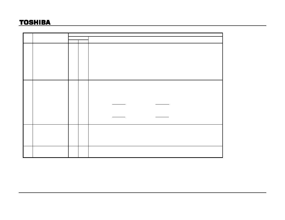
(#16 VCC = 9 V, #37 VCC = 9 V, #51 VCC = 5 V, Ta = 25 ± 3°C)
SW MODE
NOTE
ITEM
SW45 SW46
MEASUREMENT METHOD
C6
Color Difference Output
Tint Adjustment
Characteristics
B
ON
1)
Input a rainbow signal (signal C-1) to the chroma input pin (TP45).
Burst : chroma = 300 mVp-p : 300 mVp-p
2)
Measure the demodulation angles θB’ and θR’ in the outputs with the tint set to the maximum
(subaddress (03H), data (FE)). Calculate θBmax and θRmax by the following formulas.
θBmax = θB’ θBcnt
θRmax = θR’ θRcnt
3)
Measure the demodulation angles θB” and θR” in the outputs with the tint set to the minimum (subaddress
(03H), data (00). Calculate θBmin and θRmin by the following formulas
θBmin = θB″ θBcnt
θRmin = θR″ θRcnt
C7
Supply Voltage
Dependence of Color
Difference Output
B
ON
1)
Input a rainbow signal (signal C-1) to the chroma input pin (TP45).
Burst : chroma = 300 mVp-p : 300 mVp-p
2)
As in C2, measure the amplitudes VBp and VRp of the B-Y output pin (TP47) and R-Y output pin
(TP48) when the 5-V VCC is set to 5 V + 0.3 V. Calculate the amplitude ratios BVp and RVp when the 5-V
VCC is set to 5 V.
100
vB
VBp
BVp
×
=
100
vR
VRp
RVp
×
=
3)
Using the same tests as above, calculate BVn and RVn when the 5-V VCC is set to 5 V 0.3 V
100
vB
VBn
BVn
×
=
100
vR
VRn
RVn
×
=
C8
Identification Sensitivity
B
ON
1)
Input a rainbow signal (signal C-1) to the chroma input pin (TP45).Burst : chroma = 1 : 1
2)
Gradually reduce the input signal amplitude from 100 mVp-p. When the B-Y output pin (TP47) signal
disappears (when the current is DC), measure the input signal amplitude vCB.
3)
Gradually increase the input signal amplitude from 0 mVp-p. When a demodulation signal appears on the
B-Y output pin (TP47), measure the input signal amplitude vBC.
C9
Bus Read Identification
B
ON
1)
Perform the same tests as above while observing the bus read : When the input signal amplitude is vCB,
check that the first bit is set to 0 (bCB).
When the input signal amplitude is vBC, check that the first bit is set to 1 (bBC).
Note 1: Where the bus data are not specified, set the preset values.
Note 2: Ensure the sync signal is always input to TP38 (SYNC IN).
相关PDF资料 |
PDF描述 |
|---|---|
| TA1310AN | SPECIALTY CONSUMER CIRCUIT, PDIP56 |
| TA1310BN | SPECIALTY CONSUMER CIRCUIT, PDIP56 |
| TA1310N | SPECIALTY CONSUMER CIRCUIT, PDIP56 |
| TA1316AN | SPECIALTY CONSUMER CIRCUIT, PDIP56 |
| TA1317AFG | HORIZ/VERT DEFLECTION IC, PDSO30 |
相关代理商/技术参数 |
参数描述 |
|---|---|
| TA1310BM | 制造商:Panasonic Industrial Company 功能描述:SUB ONLY IC |
| TA1310BN | 制造商:Panasonic Industrial Company 功能描述:SUB ONLY IC/P-TA1310DN SUBBING WITH TA1310DN |
| TA1310DN | 制造商:Panasonic Industrial Company 功能描述:IC |
| TA1310N | 制造商:TOSHIBA 制造商全称:Toshiba Semiconductor 功能描述:NTSC VIDEO, CHROMA, DEFRECTION, AND DEC. DISTORTION COMPENSATION IC (FOR YUV INTERFACE AND ACB WITH) |
| TA131308 | 制造商:Fibox 功能描述:Bulk |
发布紧急采购,3分钟左右您将得到回复。