- 您现在的位置:买卖IC网 > PDF目录98152 > TA1310ANG SPECIALTY CONSUMER CIRCUIT, PDIP56 PDF资料下载
参数资料
| 型号: | TA1310ANG |
| 元件分类: | 消费家电 |
| 英文描述: | SPECIALTY CONSUMER CIRCUIT, PDIP56 |
| 封装: | 0.600 INCH, 1.78 MM PITCH, PLASTIC, SDIP-56 |
| 文件页数: | 62/106页 |
| 文件大小: | 2686K |
| 代理商: | TA1310ANG |
第1页第2页第3页第4页第5页第6页第7页第8页第9页第10页第11页第12页第13页第14页第15页第16页第17页第18页第19页第20页第21页第22页第23页第24页第25页第26页第27页第28页第29页第30页第31页第32页第33页第34页第35页第36页第37页第38页第39页第40页第41页第42页第43页第44页第45页第46页第47页第48页第49页第50页第51页第52页第53页第54页第55页第56页第57页第58页第59页第60页第61页当前第62页第63页第64页第65页第66页第67页第68页第69页第70页第71页第72页第73页第74页第75页第76页第77页第78页第79页第80页第81页第82页第83页第84页第85页第86页第87页第88页第89页第90页第91页第92页第93页第94页第95页第96页第97页第98页第99页第100页第101页第102页第103页第104页第105页第106页
TA1310ANG
2005-09-20
59
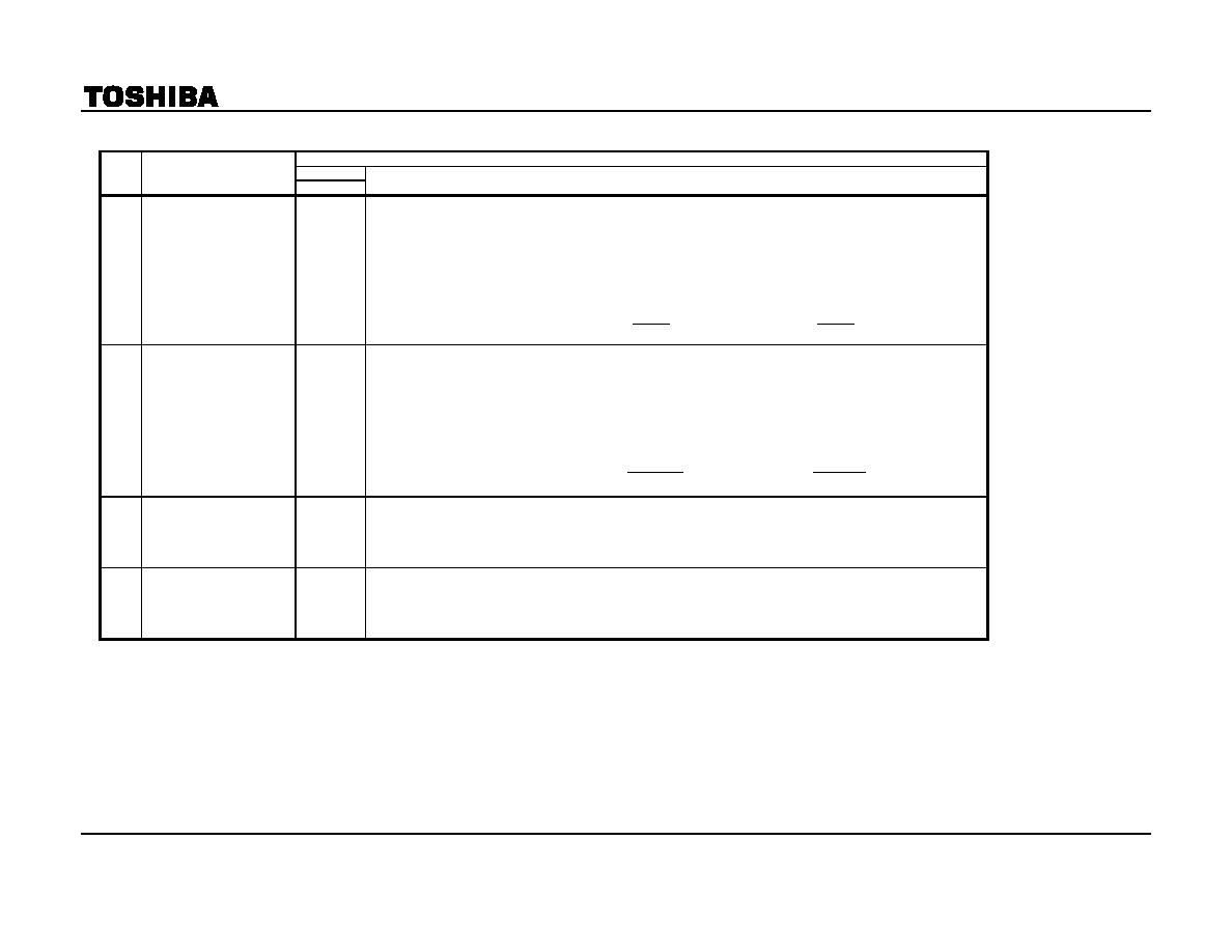
Y stage
(#16 VCC = 9 V, #37 VCC = 9 V, #51 VCC = 5 V, Ta = 25 ± 3°C)
SW MODE
NOTE
ITEM
SW45
MEASUREMENT METHOD
Y1
Sync Input~DL Output AC
Gain
A
1)
Input signal C-2 to the Sync Input pin (TP38).
f0 = 100 kHz, picture period amplitude = 0.2 Vp-p
2)
Turn DL mode off (subaddress (12), data (80)) and measure the picture period amplitude v43off of the DL output
(TP43). Calculate the gain from the input (GYoff) by the formula shown below.
3)
Turn DL mode on (subaddress (12), data (A0)) and measure the picture period amplitude v43on of the DL output
(TP43). Calculate the gain from the input (GYon) by the formula shown below.
2
0
43off
v
20Log
GYoff
.
=
2
0
43on
v
20Log
GYon
.
=
Y2
Sync Input~DL Output
Frequency Gain
A
1)
Input signal C-2 to the Sync Input pin (TP38).
f0 = 8 MHz, picture period amplitude = 0.2 Vp-p
2)
Turn DL mode off (subaddress (12), data (80)) and measure the picture period amplitude v438Moff of the DL
output (TP43). Calculate the gain from the input (GfYoff) by the formula shown below.
3)
Turn DL mode on (subaddress (12), data (A0)) and measure the picture period amplitude v438Mon of the DL
output (TP43). Calculate the gain from the input (GfYon) by the formula shown below.
43off
v
438Moff
v
20Log
GfYoff
=
43on
v
438Mon
v
20Log
GfYon
=
Y3
Sync Input~DL Output
Dynamic Range
A
1)
Input signal C-3 to the Sync Input pin (TP38).
2)
When the amplitude A of signal C-3 is increased from 0, observe the change in the picture period amplitude of
the DL output (TP43). With DL mode turned on and off, when the output amplitude stops changing in a linear
direction, measure the input signal amplitude A.
Y4
Sync Input~DL Output
Transfer Characteristics
A
1)
Input signal C-2 to the Sync Input pin (TP38).
f0 = 100 kHz, picture period amplitude = 0.2 Vp-p
2)
Turn DL mode on (subaddress (12H), data (20)) and measure the amount of delay TYLD from the Sync Input
(#38) to the DL output (TP43).
Note 1: Where the bus data are not specified, set the preset value.
Note 2: Ensure the sync signal is always input to TP38 (SYNC IN).
相关PDF资料 |
PDF描述 |
|---|---|
| TA1310AN | SPECIALTY CONSUMER CIRCUIT, PDIP56 |
| TA1310BN | SPECIALTY CONSUMER CIRCUIT, PDIP56 |
| TA1310N | SPECIALTY CONSUMER CIRCUIT, PDIP56 |
| TA1316AN | SPECIALTY CONSUMER CIRCUIT, PDIP56 |
| TA1317AFG | HORIZ/VERT DEFLECTION IC, PDSO30 |
相关代理商/技术参数 |
参数描述 |
|---|---|
| TA1310BM | 制造商:Panasonic Industrial Company 功能描述:SUB ONLY IC |
| TA1310BN | 制造商:Panasonic Industrial Company 功能描述:SUB ONLY IC/P-TA1310DN SUBBING WITH TA1310DN |
| TA1310DN | 制造商:Panasonic Industrial Company 功能描述:IC |
| TA1310N | 制造商:TOSHIBA 制造商全称:Toshiba Semiconductor 功能描述:NTSC VIDEO, CHROMA, DEFRECTION, AND DEC. DISTORTION COMPENSATION IC (FOR YUV INTERFACE AND ACB WITH) |
| TA131308 | 制造商:Fibox 功能描述:Bulk |
发布紧急采购,3分钟左右您将得到回复。