- 您现在的位置:买卖IC网 > PDF目录98169 > TC253SPD-B0 (TEXAS INSTRUMENTS INC) SPECIALTY ANALOG CIRCUIT, CDIP22 PDF资料下载
参数资料
| 型号: | TC253SPD-B0 |
| 厂商: | TEXAS INSTRUMENTS INC |
| 元件分类: | 模拟信号调理 |
| 英文描述: | SPECIALTY ANALOG CIRCUIT, CDIP22 |
| 封装: | 1.78 MM PITCH, WINDOWED, CERAMIC, DIP-22 |
| 文件页数: | 21/23页 |
| 文件大小: | 363K |
| 代理商: | TC253SPD-B0 |
TC253SPDB0
680 × 500 PIXEL IMPACTRON CCD IMAGE SENSOR
JULY 2003 SOCS084
7
POST OFFICE BOX 655303
DALLAS, TEXAS 75265
amplifier. Charge is multiplied as it progresses from stage to stage in the multiplier toward the charge detection
node. The charge multiplication level depends on the amplitude of the multiplication pulses (approximately 11
V~15 V) applied to the multiplication gates. Due to the double length of the register, the first line in the field or
frame scan does not contain valid data and should be discarded.
readout and video processing
The last element of the charge readout and detection chain is the charge detection node. The charge detection
node uses standard floating diffusion (FD) concepts followed by dual stage source followers as buffer amplifiers.
The reset gate is internally connected to SRG1. This results in simultaneous FD resets when the SRG1 gate
is clocked high. To achieve the ultimate sensor performance, it is necessary to eliminate kTC noise using CDS
processing techniques. The IMPACTRONTM devices can detect single photons when cooled or when
sufficiently short integration times are used.
absolute maximum ratings over operating free-air temperature (unless otherwise noted)
Supply voltage range, Vss: ADB (see Note 1)
SUB to SUB + 15 V
. . . . . . . . . . . . . . . . . . . . . . . . . . . . . . . . . . . . .
Supply voltage range, Vss: ODB
SUB to SUB + 20 V
. . . . . . . . . . . . . . . . . . . . . . . . . . . . . . . . . . . . . . . . . . . . . . . .
Input voltage range, VI: IAG, SAG, SRG2
8 V to + 8 V
. . . . . . . . . . . . . . . . . . . . . . . . . . . . . . . . . . . . . . . . . . . . .
Input voltage range, VI: SRG1
5 V to + 8 V
. . . . . . . . . . . . . . . . . . . . . . . . . . . . . . . . . . . . . . . . . . . . . . . . . . . . . . .
Input voltage range, VI: CMG
5 V to + 15 V
. . . . . . . . . . . . . . . . . . . . . . . . . . . . . . . . . . . . . . . . . . . . . . . . . . . . . . .
Supply voltage range, Vcool: P+ (see Note2)
0 V + 3 V
. . . . . . . . . . . . . . . . . . . . . . . . . . . . . . . . . . . . . . . . . . . . . .
Supply current range, Icool: P+ (see Note2)
0 mA to 700 mA
. . . . . . . . . . . . . . . . . . . . . . . . . . . . . . . . . . . . . . . . .
Operating free-air temperature range, TA
10
°C to 45°C
. . . . . . . . . . . . . . . . . . . . . . . . . . . . . . . . . . . . . . . . . . . .
Storage temperature range, TSTG
30
°C to 85°C
. . . . . . . . . . . . . . . . . . . . . . . . . . . . . . . . . . . . . . . . . . . . . . . . . . .
Operating case temperature range
10
°C to 55°C
. . . . . . . . . . . . . . . . . . . . . . . . . . . . . . . . . . . . . . . . . . . . . . . . . .
Stresses beyond those listed under “absolute maximum ratings” may cause permanent damage to the device. These are stress ratings only, and
functional operation of the device at these or any other conditions beyond those indicated under “recommended operating conditions” is not
implied. Exposure to absolute-maximum-rated conditions for extended periods may affect device reliability.
NOTES:
1. All voltage values are with respect to substrate terminal.
2. Peltier cooler generates heat during cooling process. To keep case temperature range, the heat must be removed through external
heat sink.
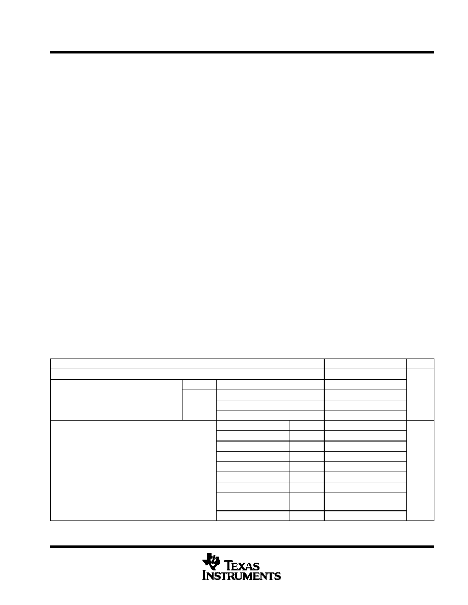
recommended operating conditions
MIN
NOM
MAX
UNIT
Substrate bias, VSS
0
ADB
11.5
12
12.5
S ppl
oltage V
For blooming control (see Note 3)
4.3
5.3
6.3
V
Supply voltage, VDD
ODB
For clearing
12
12.5
13
V
ODB
For transfer (see Note 4)
3.8
4.8
5.8
IAG1
High
4.9
5.2
5.5
IAG2, SAG1, SAG2
High
2.8
3.1
3.4
IAG1, SAG1
Low
6.3
6
5.7
IAG2, SAG2
Low
7
6.7
6.4
Input voltage VI
SRG1, SRG2
High
4.6
4.9
5.2
V
Input voltage, VI
SRG1
Low
4.6
4.3
4
V
SRG2
Low
5.8
5.5
5.2
CMG (see Note 5)
High
(Gain)
7
(1)
14.5
(30)
15
(100)
Low
3.1
2.8
2.5
相关PDF资料 |
PDF描述 |
|---|---|
| TC255 | SPECIALTY ANALOG CIRCUIT, CDIP8 |
| TC2574-VOETR | 1.8 A SWITCHING REGULATOR, 63 kHz SWITCHING FREQ-MAX, PDSO16 |
| TC2575-12.0VAT | 3.2 A SWITCHING REGULATOR, 63 kHz SWITCHING FREQ-MAX, PSFM5 |
| TC271-40 | SPECIALTY ANALOG CIRCUIT, CDIP22 |
| TC33025VOETR | 2 A SWITCHING CONTROLLER, 1000 kHz SWITCHING FREQ-MAX, PDSO16 |
相关代理商/技术参数 |
参数描述 |
|---|---|
| TC254 | 制造商:Cooper Wiring Devices 功能描述: |
| TC2540 | 功能描述:铝质电解电容器 - 带引线 4000uF 25Volts RoHS:否 制造商:Kemet 引线类型: 电容:220 uF 容差:20 % 电压额定值:25 V 工作温度范围: 端接类型:Radial 外壳直径:8 mm 外壳长度:11 mm 引线间隔:5 mm 产品:General Purpose Electrolytic Capacitors 封装:Bulk |
| TC2540A | 制造商:CDE 制造商全称:Cornell Dubilier Electronics 功能描述:Axial Leaded Aluminum Electrolytic Capacitors |
| TC254P | 制造商:Texas Instruments 功能描述: |
| TC255 | 制造商:TI 制造商全称:Texas Instruments 功能描述:336- 】 244-pixel ccd image sensor |
发布紧急采购,3分钟左右您将得到回复。